Anthracene inverse-design cavity: stopped at the Q-observability gate
Outcome
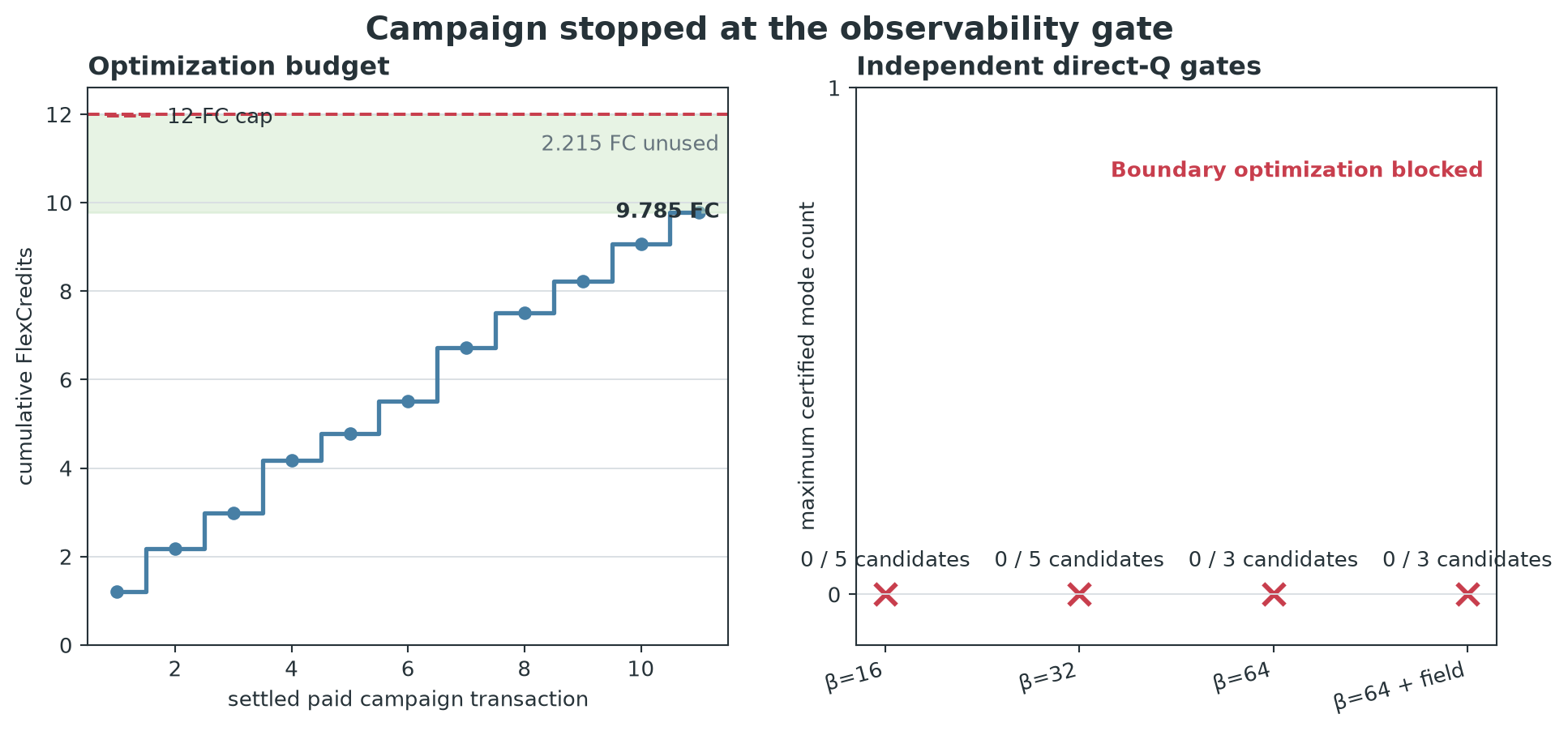
The Q≥25,000 target was not achieved. The inverse-design stage produced a nearly binary, feedthrough-connected Si3N4 structure in the requested stack, and both of its differentiable surrogate objectives improved. However, four independent direct-Q scans covering 16 gray or contour handoffs found zero certified resonances. Because there was no observable pole to track, the free-form boundary optimizer was not launched and no post-boundary geometry exists.
This is not a RAM failure or a hidden high-Q claim. Each final ringdown used a 35 nm fixed Cartesian mesh, double precision, 15 ps runtime, 12 probes, no early shutoff, and 6,800,640 full-domain cells before x/y symmetry reduction. The Tidy3D jobs completed normally. The failure is in cavity creation and objective alignment: the adjoint surrogates learned wavelength-selective scattering and local field enhancement without creating measurable stored energy.
The optimization ledger settled at 9.7851 of 12 FlexCredits, leaving 2.2149 FC unused. The separately authorized 2.5-FC final-evaluation ledger was never created because there was no fully Q-optimized frozen geometry to evaluate.
Physical stack and source
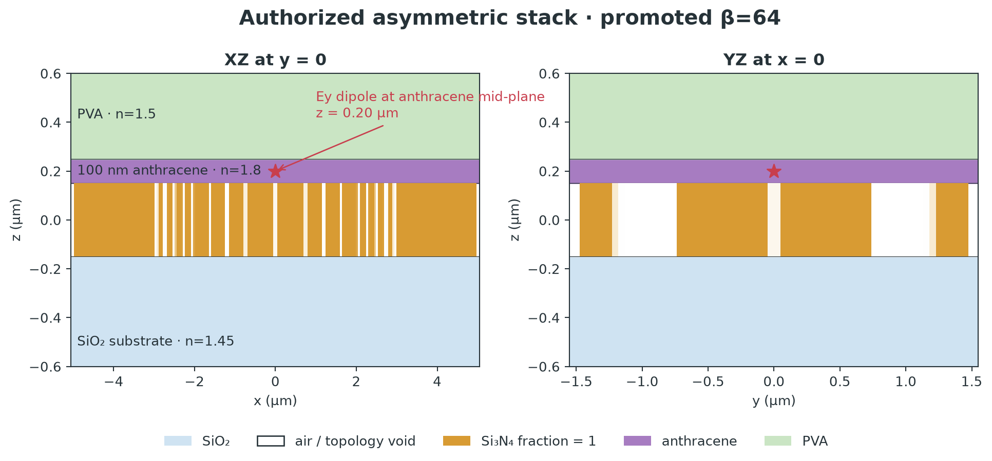
The simulated contract was:
- a SiO2 substrate with n=1.45;
- a 300 nm patterned Si3N4 layer with n=2.0 and air in its gaps and lateral voids;
- a uniform 100 nm anthracene film with n=1.8;
- an Ey dipole at
(x, y, z) = (0, 0, 0.20) µm, exactly at the anthracene mid-plane; - PVA upper cladding with n=1.5;
- no vacuum aperture; and
- a 10 × 3 µm design region with 700 nm feedthrough guides and x/y symmetry.
The preflight sampled epsilon=3.24 at the source, exactly 1.8²; the dipole
was not in air.
What inverse design produced
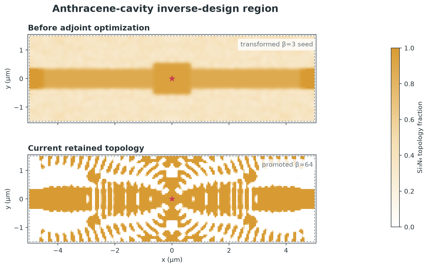
The weak seed was only a feedthrough guide and central pad. Projection continuation at beta=3, 8, 16, 32, and 64 formed a cavity-like distributed pattern and reduced the fraction of pixels between 0.1 and 0.9 from 84.67% to 6.57%. The final threshold-0.50 conversion yielded 84 exact contours with zero reported density-to-contour round-trip mismatch.
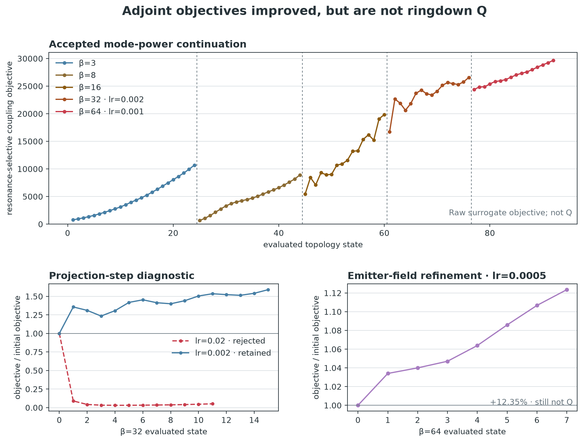
The initial mode-power contrast surrogate rose from 768.8 to 29,662.6 over the accepted continuation. A beta-32 learning rate of 0.02 collapsed the surrogate and was rejected; repeating at 0.002 recovered and improved it. The subsequent emitter-field contrast objective rose monotonically by 12.35%. These are real adjoint improvements, but neither metric is Q.
| Paid stage | Evaluated states / candidates | Retained result | Gray fraction | Actual FC |
|---|---|---|---|---|
| beta=3 mode-power adjoint | 24 | 768.8 → 10,670.8 | 84.67% | 1.2000 |
| beta=8 mode-power adjoint | 20 | 650.7 → 8,893.9 | 44.87% | 0.9750 |
| beta=16 mode-power adjoint | 16 | 5,447.2 → 19,855.4 | 25.33% | 0.8000 |
| beta=16 Q scan | 5 | 0 certified modes | — | 1.2074 |
| beta=32 high-rate diagnostic | 12 | best state was index 0; later value 852.9 | 13.10% | 0.6000 |
| beta=32 corrected adjoint | 16 | 16,710.4 → 26,562.4 | 13.40% | 0.7250 |
| beta=32 Q scan | 5 | 0 certified modes | — | 1.2074 |
| beta=64 corrected adjoint | 16 | 24,374.0 → 29,662.6 | 6.60% | 0.7896 |
| beta=64 Q scan | 3 | 0 certified modes | — | 0.7244 |
| beta=64 emitter-field adjoint | 8 | 1.2880e10 → 1.4471e10 | 6.57% | 0.8320 |
| final Q scan | 3 | 0 certified modes | — | 0.7244 |
Boundary handoff and the missing post-boundary result
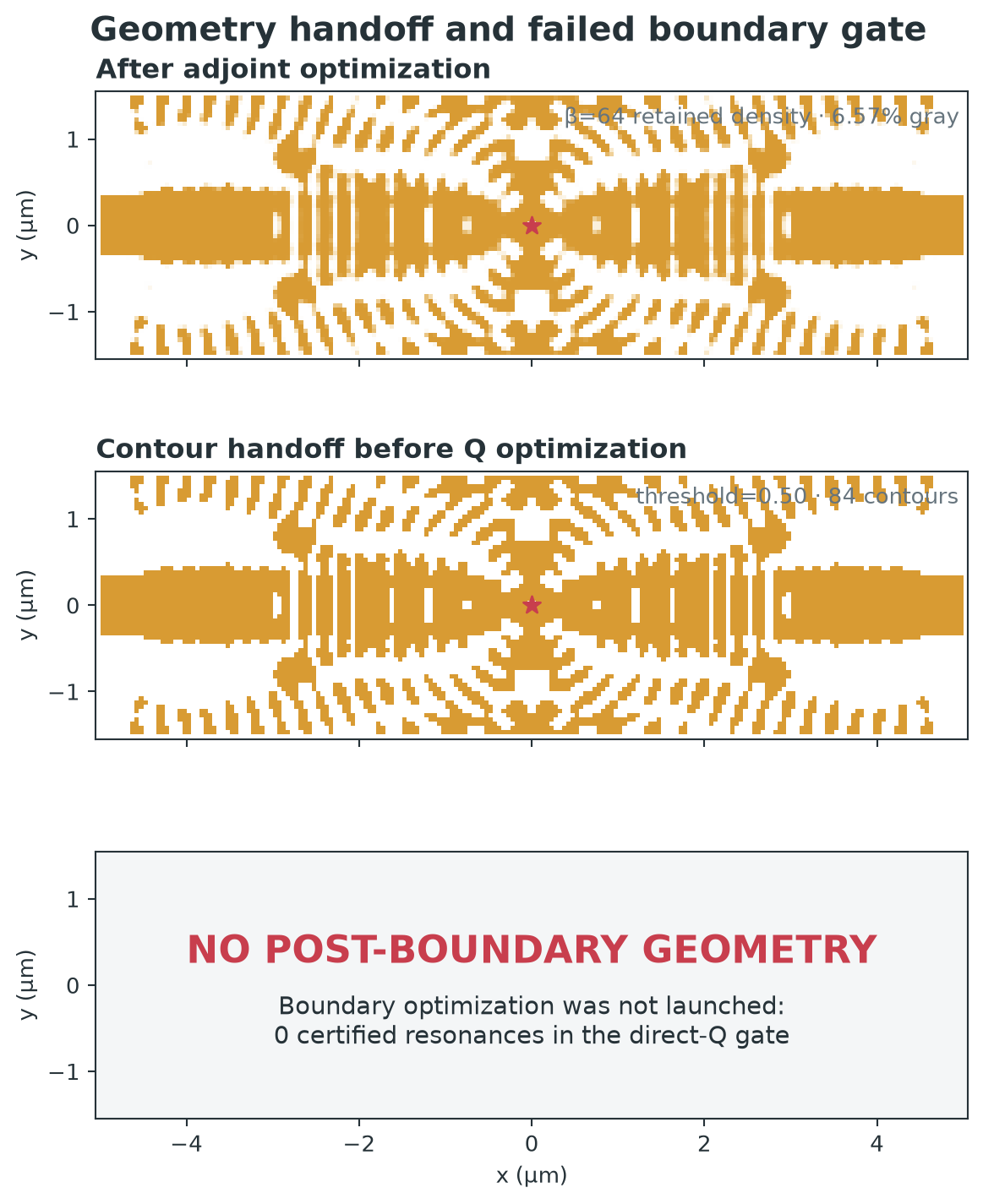
The contour machinery worked: the final density became a signed-distance field and exact polygon set suitable for smooth normal motion. But a boundary-Q step requires a baseline pole whose frequency and decay can be tracked under positive and negative perturbations. With zero certified modes, any finite difference or QNM boundary direction would have been a fit-to-noise direction. Stopping here protected both the scientific claim and the remaining budget.
Field and ringdown evidence
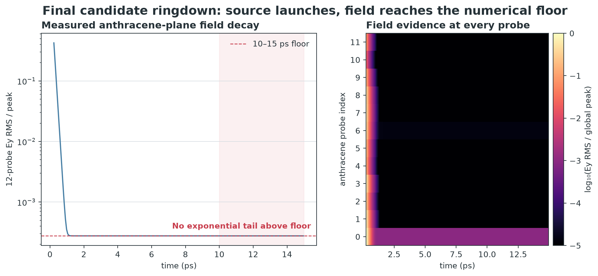
The final point dipole launched substantial field: the largest sampled
|Ey| was 742.97. After 2 ps, the collective RMS was 0.109626; after 10 ps it
was still 0.109626. That unchanged late amplitude is a numerical floor, not an
exponential cavity tail. Multi-window, multi-probe Tidy3D ResonanceFinder
therefore returned zero certified modes at every threshold. A resonant spatial
field map is intentionally absent because no resonant frequency was available
at which such a map would be meaningful.
Diagnosis
The evidence rules out several tempting explanations:
- Not the old source-placement error: the emitter is inside anthracene.
- Not insufficient RAM: all 16 fixed-grid Q jobs completed, with no memory failure.
- Not merely binarization loss: beta=16, beta=32, beta=64, and the final 6.57%-gray design all failed before and after thresholding.
- Not a dead source or monitor: every one of the 12 probes received the prompt field.
The supported explanation is objective mismatch. Target-to-sideband output mode power can improve by interference, routing, and selective scattering. Even point-field contrast at three real frequencies can increase through a prompt near-field response. Neither objective directly rewards electromagnetic energy stored after the source is gone, so both can improve while ringdown Q remains unobservable.
Recommended restart
The next paid campaign should not extend this seed with more boundary motion. It should first make the cavity-creation objective pass an observability gate:
- Validate the exact 35 nm, 12-probe ringdown protocol on a known resonant positive-control nanobeam in this same substrate/anthracene/PVA stack.
- Replace pure spectral contrast with a differentiable stored-energy/loss
objective, such as
omega * U_design / P_out, while retaining a minimum TE0 feedthrough-coupling constraint. Use a closed flux surface or explicit radiation/output channels so prompt field cannot masquerade as storage. - Add a weak fixed Bragg/stop-band scaffold outside the inverse-design defect region. The adjoint still creates the cavity and coupling section, but it no longer has to discover both a bandgap and a defect from a uniform guide in one short budget.
- Run a short direct ringdown every continuation stage and retune the adjoint frequency to the measured pole. Do not continue projection unless at least one mode is consistent across probes and fit windows.
- Begin contour optimization only after a conservative baseline Q (for example Q>1,000) is independently observable. Then require direct positive and negative boundary controls before trusting each QNM-gradient step.
This turns ringdown from a final surprise into a campaign invariant.
Reproducibility
The retained campaign, exact simulation inputs, result summaries, raw
SimulationData, credit decisions, and ledger are under
engines/atom_fishbone_coupler/campaigns/anthracene_cavity_q25k_v1/. The
visual manifest
hashes every plotted source and output. The machine-readable campaign outcome
is retained as campaign_outcome.json in the campaign directory.