Device23 continuous free-form surrogate-Q optimization
This trajectory is rejected as a physical Q optimization
Matched checkpoint evaluations found that Tidy3D Q fell from 923.53 at step 2 to 822.88 at step 10 while frozen-mesh FEM Q increased. The service remains stopped. See the first-principles trust rebuild and replacement optimizer.
What this run does
This campaign starts from the FDTD-qualified 40-hole Device23 geometry and
moves both the complete hole contours and the outer waveguide sidewalls to
maximize quality factor. The upper wall is explicit in the half-domain level
set and the lower wall follows by mirror symmetry. Sidewall motion is fully
free for |x| <= 4.5 µm, tapered smoothly to zero, and pinned for
|x| >= 4.9 µm, leaving uniform input/output leads for the PML and ports.
The level-set half-domain extends to y = 0.60 µm, providing about 322 nm
of outward travel beyond the initial 278 nm half-width rather than inheriting
the narrow padding of the old holes-only representation.
The local complex-pole FEM calculation is deliberately treated as a surrogate.
Its single objective is log(Q); mode volume and coupling are not part of the
objective.
The original holes-only service was stopped before it accepted a step. Its
step-zero checkpoint was then promoted to a complete SiN occupancy level set,
so the resumed trajectory has no hidden handoff or lost optimization history.
The production mesh smoke test passed with 1,014,895 unknowns and 261,985
elements (36.9 s to build), below the existing 1.1-million-unknown ceiling.
The Tidy3D dry build contains one 2,052-vertex free-sidewall SiN polygon and 40
air-hole polygons, retains (1, -1, 0) symmetry, and has no mesh overrides.
Neither validation consumed FlexCredits. Exact checks and artifact hashes are
recorded in sidewall_validation.json in the run directory.
The resumed production pole evaluation then returned Q = 1571.86 at
757.0 nm, localization 0.7009, and all 41 boundary-density arrays
(40 holes plus 1 mirrored sidewall curve). It used 1,053,982 unknowns and
peaked at 36.7 GB RAM. This is direct evidence that the sidewall is part of the
shape derivative, rather than only appearing in the plot or CAD conversion.
The optimizer follows the QNM shape derivative of the complex resonance. Fixed-connectivity ALE screens the local direction, but ALE improvement alone is not sufficient: the exact level-set checkpoint reconstructed from the applied mesh motion must also improve on a paired deterministic fresh remesh. That checkpoint-remesh Q is the recorded objective. Basic geometry validity, a 70 nm minimum feature, bounded boundary-transfer error, and fail-closed pole continuation prevent silent optimization of a broken device or another mode.
Projected-line-search failure and correction
The first implementation accepted step 1 (Q: 1571.9 -> 1891.5) and later
accepted step 2 (Q: 1891.5 -> 2047.8), but rejected nearly every intervening
trial. This was not a valid test of the positive Q shape gradient. Every trial
was passed through another smoothing, signed-distance reinitialization, and
island-pruning projection. An explicit zero-step audit at checkpoint 1 found
that this transform moved hole contours by as much as 1.805 nm even when
the requested gradient displacement was zero. Consequently, halving the trust
amplitude did not make the candidate converge to the incumbent. A 0.05 nm
trial also selected a different pole near 746.6 nm instead of the tracked
branch near 757 nm.
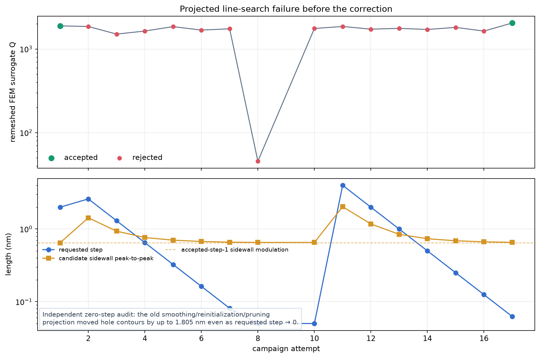
Top: remeshed FEM Q for every old attempted step, with accepted trials in
green. Bottom: requested amplitude and absolute sidewall modulation. The
requested amplitude tends to zero while the projected candidate retains a
finite geometry change. Source: optimizer_history.jsonl; the zero-step
geometry audit was recomputed from field_step_000001.npz. Generator:
plot_line_search_diagnosis.py; numerical provenance:
line_search_diagnosis.json.
The replacement has the following enforced behavior:
candidate(0)is bitwise identical to the incumbent.- A trial is one Hamilton–Jacobi advection along the pure
log(Q)shape gradient. Curvature flow is disabled because it was not part of the accepted objective. - Trial geometry is not smoothed, reinitialized, or pruned. Grid scattering is calibrated so the realized maximum normal displacement is within 5% of the requested trust amplitude before a Maxwell solve begins.
- Telemetry records the intended and realized first-order
Δlog(Q), separate hole and sidewall contributions, Hausdorff and normal displacement, remeshed actual gain, mesh-DOF change, expected pole, and tracking error. - On restart, the accepted complex pole is reconstructed from its measured
wavelength and Q. For each trial, the first-order complex-frequency shift is
added to that pole; the eigensolver chooses the nearest qualified candidate
within
0.005 / µmand localization>= 0.55. Absence of that branch fails closed instead of selecting another localized resonance.
The service was stopped after old-policy step 2. An isolated corrected 0.5 nm
production probe started from Q = 2047.77. It realized 0.499 nm maximum
normal motion, retained the tracked pole with 0.000180 / µm error and
predicted Δlog(Q) = +0.02779, of which +0.02628 came from holes and
+0.00151 from the sidewall. Nevertheless, an independently regenerated mesh
changed by −14,594 DOFs and measured Q = 1827.00, or
Δlog(Q) = −0.11407. This is a clean failure of remeshed acceptance, not a
positive-gradient trial: zero-step identity, direction purity, realized
motion, localization, and pole continuation all passed their gates.
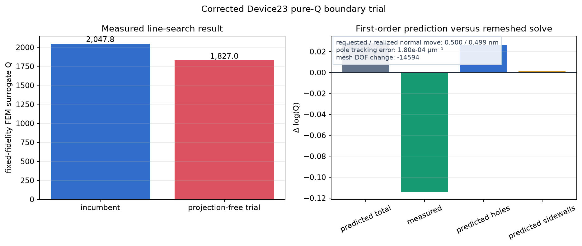
Left: incumbent and trial Q from independent fixed-fidelity FEM meshes.
Right: realized first-order Δlog(Q) prediction, remeshed measurement, and
hole/sidewall prediction split. Source: correction_probe.json; generator:
plot_correction_probe.py; exact source hash and plotting provenance:
correction_probe_figure.json.
The first correction used a fixed-connectivity ALE candidate solve as the
local sign test. The incumbent mesh nodes move with all 41 contours while
material tags and DOF numbering remain unchanged. Candidate promotion required
the interpolated mesh motion to reproduce the intended wall motion to 20%
worst-point and 2.5% RMS relative error. The first ALE pole solve raised Q to
2112.34 with the correct sign, but its narrow-band mesh extension missed that
transfer gate (59.6%); it was not promoted. A first extension audit reduced the
error to 19.6% (2.06% RMS). A four-cell plateau passed the bounded transfer
gate at 18.9% worst and 1.87% RMS. The optimizer contracts the gradient with
that applied motion, rather than the requested motion, before predicting
the Q and complex-pole changes. The repeated production gate predicted
Δlog(Q) = +0.02815 and measured +0.02597 on the fixed mesh (ratio 0.923),
raising Q from 2047.77 to 2101.64. All geometry, transfer, localization,
residual, and complex-pole checks passed, so this became accepted step 3.
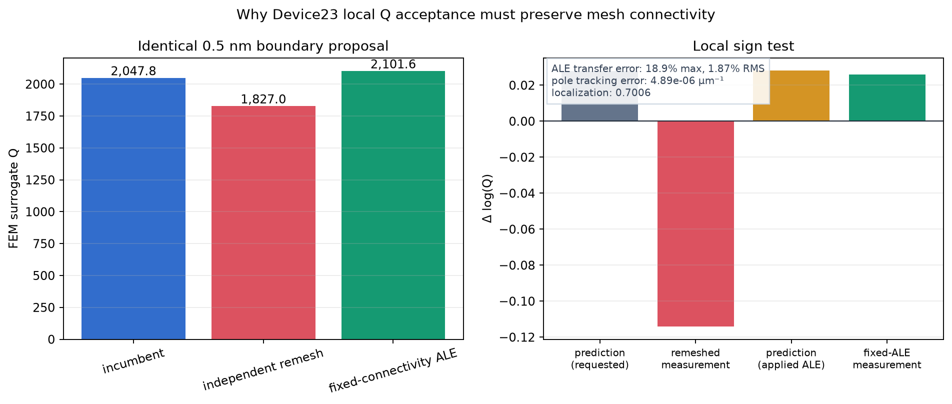
The same projection-free 0.5 nm boundary proposal evaluated three ways.
Left: incumbent, independently remeshed candidate, and fixed-connectivity ALE
Q. Right: first-order and measured Δlog(Q) for the remeshed and applied-ALE
motions. Source: correction_probe.json and correction_ale_gate_v2.json;
generator: plot_ale_acceptance.py; exact hashes and numerical provenance:
ale_acceptance_figure.json.
The persistent campaign was then resumed under fixed-ALE-only acceptance. That
exposed a second handoff error: the ALE solve evaluates its smooth VectorH1
mesh displacement, but production saved the requested level-set contour. On
the next iteration, remeshing accepted step 3 reproduced only Q = 1754.48,
not the recorded 2101.64; the next handoff similarly changed 1806.19 to
1721.29. The comparable fresh-mesh sequence was therefore decreasing.
The service was stopped and steps 3--5 were marked superseded and moved under
superseded/ale_only_handoff_v1/; no evidence was deleted. Step 2
(Q = 2047.77) is again the active checkpoint. The second correction writes
the normal motion actually sampled from ALE back into the level set without
double-applying the sidewall lead taper, then evaluates that exact checkpoint
on a fresh deterministic mesh. Both the ALE gain and checkpoint-remesh gain
must be positive, and an incumbent rebaseline mismatch above 2% fails closed.
A production-fidelity 0.5 nm audit demonstrated the new gate. The local ALE
solve again increased Q to 2101.64 (Δlog(Q) = +0.02597), while the exact
saved checkpoint remeshed to 1763.88 (Δlog(Q) = -0.14923). Localization
was 0.7013, the relative residual was 3.75e-12, and pole tracking passed;
the step was correctly rejected. The ALE-to-checkpoint motion mismatch was
13.3% worst-point and 0.91% RMS. The two million-DOF solves are sequential:
resident memory fell from about 33 GB to 2.7 GB between them, so the gate fits
the 45 GiB host without holding both meshes at once.
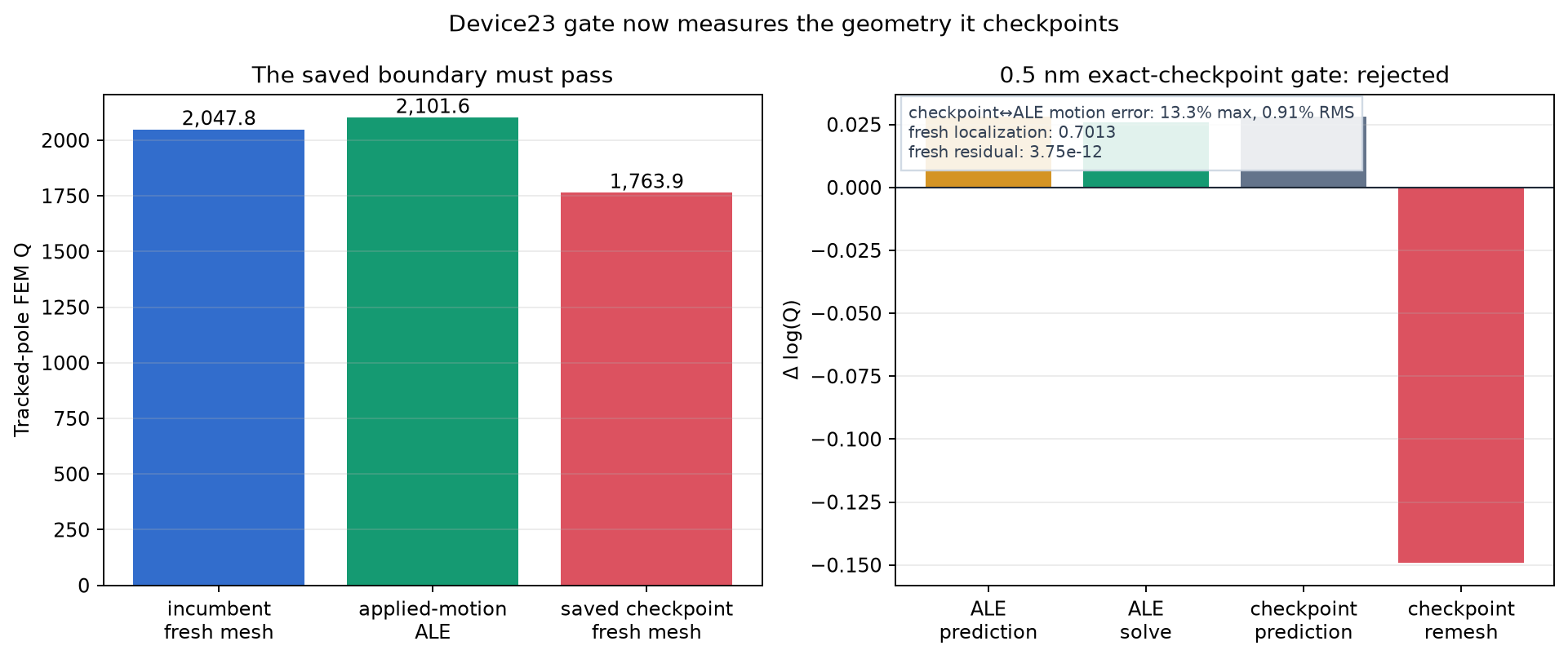
The new fail-closed gate for the same 0.5 nm proposal. Left: fresh incumbent,
applied-motion ALE, and the freshly remeshed checkpoint actually written to
disk. Right: predicted and solved Δlog(Q) for ALE and checkpoint paths. The
checkpoint loses Q and is rejected. Source: handoff_v2_probe.json; generator:
plot_exact_checkpoint_gate.py; hash and plotting provenance:
exact_checkpoint_gate_figure.json.
The supervised campaign restarted from step 2 at 0.25 nm. Its first complete
production decision independently reproduced the corrected behavior: the ALE
solve increased Q to 2074.98 (Δlog(Q) = +0.01320), but the exact saved
checkpoint returned 1579.98 (Δlog(Q) = -0.25934) and was rejected. The
fresh incumbent rebaseline agreed to 1.1e-12 in log Q, localization was
0.6998, the relative residual was 1.08e-11, and only 20 Maxwell DOFs
changed. The service retained step 2 exactly and halved the next trial to
0.125 nm. This decision consumed no FlexCredits.
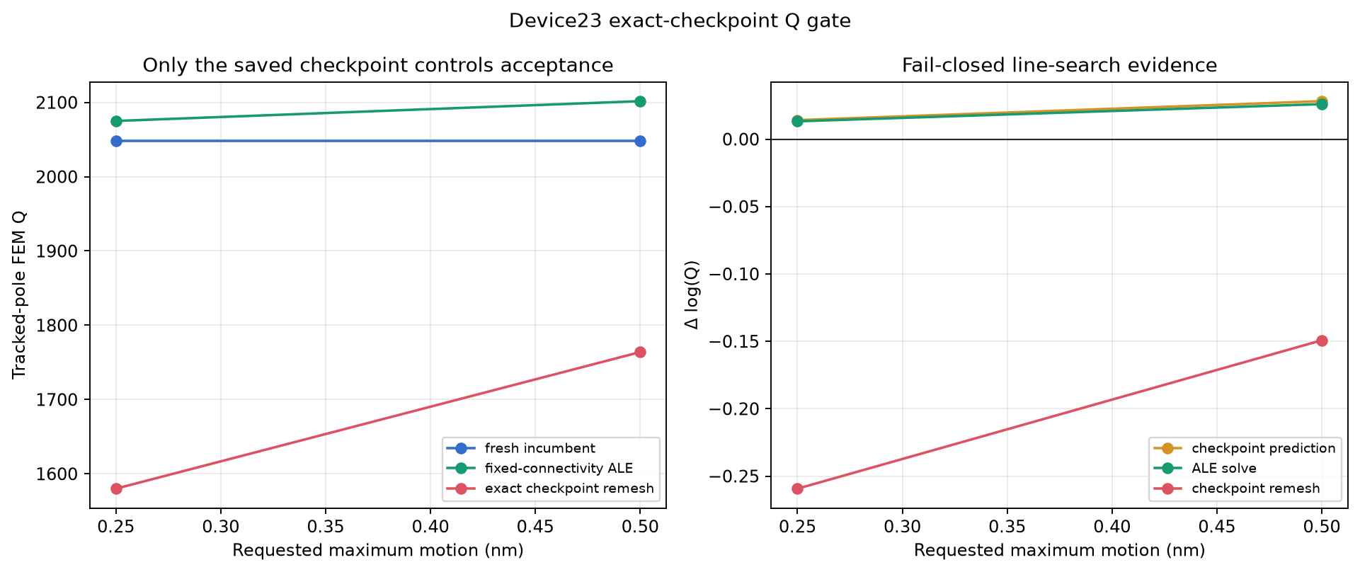
Fresh incumbent, applied-motion ALE, and exact-checkpoint remesh Q for the
0.5 nm standalone audit and 0.25 nm first supervised attempt, with their
predicted and solved log-Q gains. Sources: handoff_v2_probe.json and
batch_00006.json; generator: plot_exact_checkpoint_series.py; source hashes
and plotting provenance: exact_checkpoint_series_figure.json.
Persistent-reference repair and sustained ascent
The exact-checkpoint gate was safe but could not optimize: at 0.25, 0.125, 0.0625, and 0.05 nm, the same-connectivity ALE gain approached zero normally while the separately remeshed checkpoint retained a finite negative bias. The service stopped at its 0.05 nm floor without moving the trusted step-2 geometry. This demonstrated a discretization floor, not a failed shape derivative.
The production optimizer now freezes the deterministic step-2 connectivity
(1,009,435 Maxwell DOFs and 260,038 elements). Every later incumbent and trial
is represented as an absolute ALE deformation of that one reference mesh.
This remains restartable without serializing a 30 GB process: a restart rebuilds
the deterministic reference, reapplies the incumbent's total deformation, and
must reproduce its recorded log Q within 1e-5. The candidate then uses the
same connectivity, material tags, and DOF numbering. Remeshed level sets remain
the geometry visualization, fabrication, and Tidy3D handoff, but do not decide
local acceptance.
The persistent gate is fail-closed on all of the following:
- positive measured log-Q gain;
- incumbent Q replay and predicted-pole continuation;
- localization and eigensolver residual;
- 70 nm minimum feature;
- absolute boundary-transfer error;
- every deformed element's integration measure, limited to 0.35--3.0 times its undeformed reference value.
The first production-fidelity step requested 0.25 nm and passed every gate.
The incumbent replayed Q = 2047.7660544924, differing from its recorded Q by
only 1.07e-12 in log Q. The derivative predicted
Δlog(Q) = +0.01391597; the common-connectivity pole solve measured
+0.01320426 (94.9% agreement), reaching Q = 2074.9846 at 756.954 nm.
Localization was 0.70054, residual 1.10e-14, and pole-tracking error
1.05e-6 / µm. Deformed element measures remained between 0.9845 and 1.0192
times their reference values. This became accepted step 3. The frozen
reference artifact is byte-identical to field_step_000002.npz.
A second consecutive step then requested 0.325 nm. The incumbent replayed at
Q = 2074.9846045680 with only 3.04e-14 log-Q error. The shape derivative
predicted Δlog(Q) = +0.01756777; the common-connectivity pole solve measured
+0.01655417 (94.2% agreement), reaching Q = 2109.6201 at 756.922 nm.
All ten gates passed: localization was 0.70057, residual 2.19e-14, pole
tracking error 1.88e-6 / µm, and cumulative element measures remained
between 0.9642 and 1.0438 times the reference. The minimum feature remained
75.53 nm. This became accepted step 4 and demonstrates repeatable ascent after
cumulative arbitrary-boundary motion, rather than a one-step-only result.
This step also exposed and repaired an NGSolve implementation limit. Its complex vector-array coefficient evaluator allocates a hard-coded 1,000-byte local heap per point, which overflowed while sampling the deformed high-order H(curl) field on 62,940 wall quadrature samples. Production now evaluates the real and imaginary coefficient functions through NGSolve's larger real-array path, recombines them exactly, blocks calls, and retains a scalar fallback. The repair is regression-tested and does not change the Maxwell operator or the accepted objective.
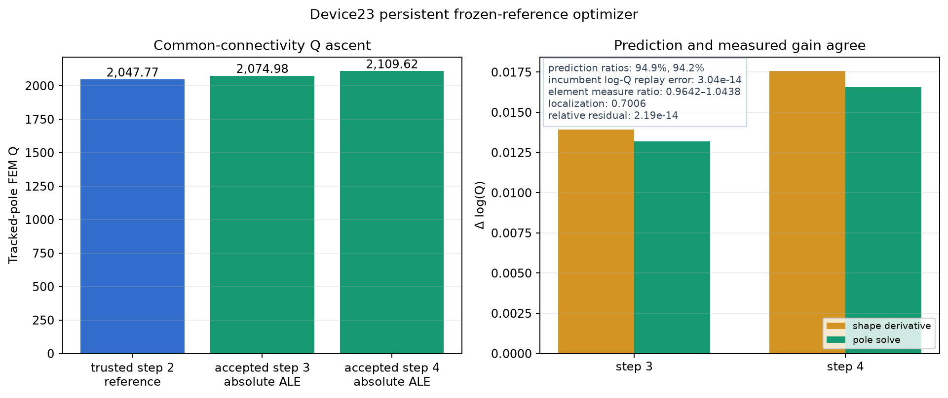
Left: two consecutive tracked FEM Q improvements on the identical reference
connectivity. Right: predicted and measured log-Q gain for accepted steps 3
and 4, with restart-replay, element-measure, localization, and residual
diagnostics. Sources: persistent_ale_probe.json and batch_00010.json;
generator:
plot_persistent_ale_acceptance.py; source hash and plotting provenance:
persistent_ale_acceptance_figure.json.

Trusted step-2 complete-material level set used to create the frozen
connectivity, shown with the same axes and Si₃N₄/air legend as the live current
geometry. Source: persistent_reference_field.npz; generator:
plot_geometry.py.
This first campaign uses normalized shape-gradient ascent with an adaptive normal-displacement amplitude, not BFGS. Ordinary BFGS coordinates are not stable when level-set contours are resampled or change topology; a future L-BFGS variant should first transport each gradient to a fixed grid or fixed basis and reset its history after topology events. Predicted-pole continuation allows the resonance to drift by many linewidths without turning the problem back into fixed-frequency optimization.
Every 10 accepted boundary steps, the current checkpoint is converted to one
SiN PolySlab exterior plus 40 air-hole PolySlab contours and measured by a
diagnostic ringdown. These FDTD points are plotted beside the surrogate
trajectory but cannot accept, reject, or roll back a step. The FDTD campaign
has a separate 5 FlexCredit cap. It uses GridSpec.auto at 14 steps per
wavelength with no mesh override regions.
The process is persistent and resumes from its newest accepted level-set
checkpoint. It runs until the service is stopped or a STOP file is placed in
the run directory.
Live visual record

Initial geometry after the zero-cost representation handoff, top view. Si₃N₄
and air are shown on fixed x/y axes. The straight outer walls are now part of
the same material level set as the 40 holes. Source: promoted
field_step_000000.npz; the pre-promotion field is retained beside it.

Most recent accepted hole-and-sidewall geometry, using exactly the same axes
and material legend as the initial panel. The image is regenerated from the
latest field_step_NNNNNN.npz checkpoint.
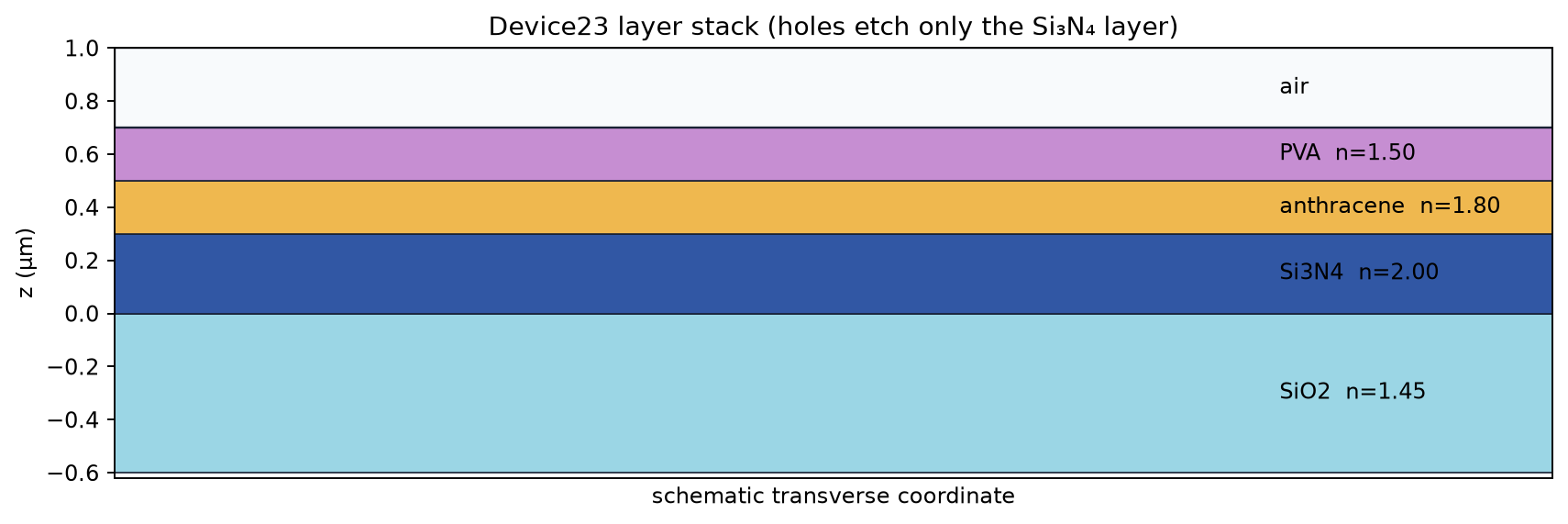
Cross-section of the numerical layer stack. The air holes etch the 300 nm Si₃N₄ layer; the substrate, anthracene, and PVA films remain uniform.
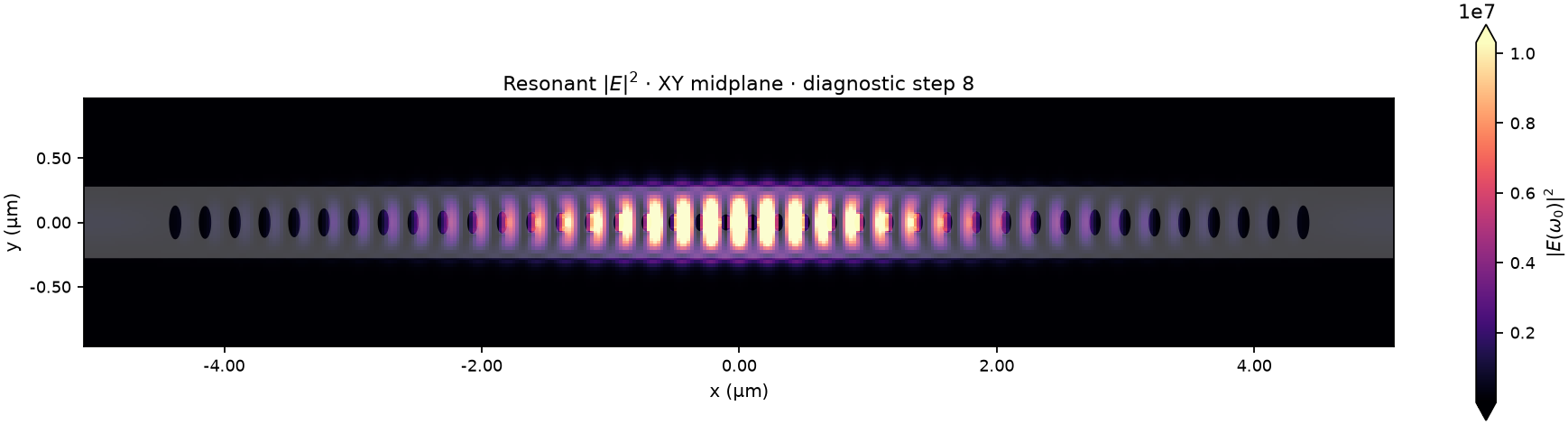
Latest Tidy3D XY-midplane field. The plotted quantity is the Hann-projected resonant vector intensity \(|E(\omega_0)|^2\), with a robust per-panel color scale and geometry overlay. Before accepted step 10, this is the FDTD-qualified launch-seed field.
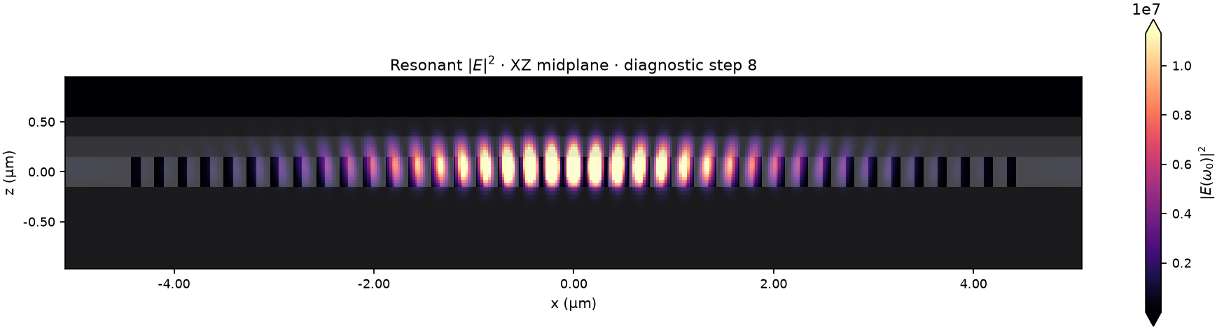
Corresponding XZ-midplane resonant intensity at the same fitted frequency and
with the same temporal projection. Exact wavelength and monitor-window metadata
are written to dashboard/field_meta.json after each new diagnostic.
Reproducibility
The campaign implementation and plot generators are under
engines/quan_loncar_meep_lab/campaigns/device23_surrogate_freeform_q/.
Persistent artifacts are under
engines/quan_loncar_meep_lab/runs/20260812T131106Z_device23_surrogate_freeform_q/.
The live dashboard exposes the complete recent step history, surrogate and
FDTD Q trajectories, budget ledger, matched geometry panels, and most recent
FDTD fields.