Si3N4 inverse-design → free-form-Q pipeline — 2026-08-11
Outcome
The end-to-end pipeline ran successfully as software, but it did not meet the physical success criterion. Tidy3D inverse design produced and binarized a general Si3N4/SiO2 collector around the exact 1 µm vacuum aperture. That design was converted to exact perturbable polygon boundaries and subjected to three different Tidy3D-adjoint boundary objectives. The final independent 24 ps Tidy3D certificate measured only
at 781.39584 nm, not the required 25,000. The result passes the retained multi-probe/multi-window certificate, with 4.93% full Q spread and 0.836% maximum harmonic-inversion error.
This is a useful negative result: the persistent Q plateau is now localized to the objective/physics interface rather than RAM, contour conversion, or a failure to run arbitrary boundaries.
Visual evidence
Geometry through the complete pipeline
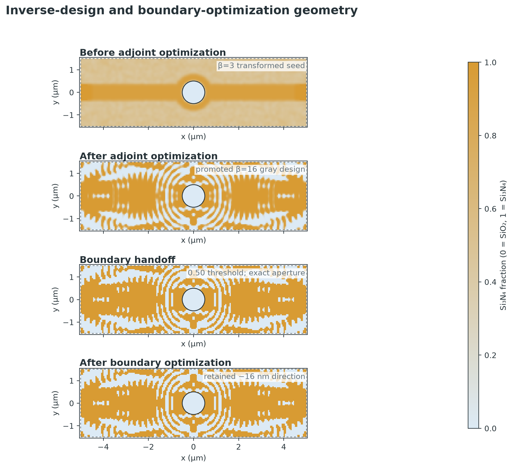
All four panels use the same 10 × 3 µm axes and material scale. The first is
the transformed beta-3 seed in topology_run/initial_topology.npz; the second
is the promoted continuous beta-16 state; the third is its 0.50-threshold
boundary handoff; and the fourth is the retained −16 nm survival-direction
candidate. The exact 1 µm aperture is protected at every stage. The final two
panels look nearly identical at device scale because the largest control
motion is only 17.2 nm.
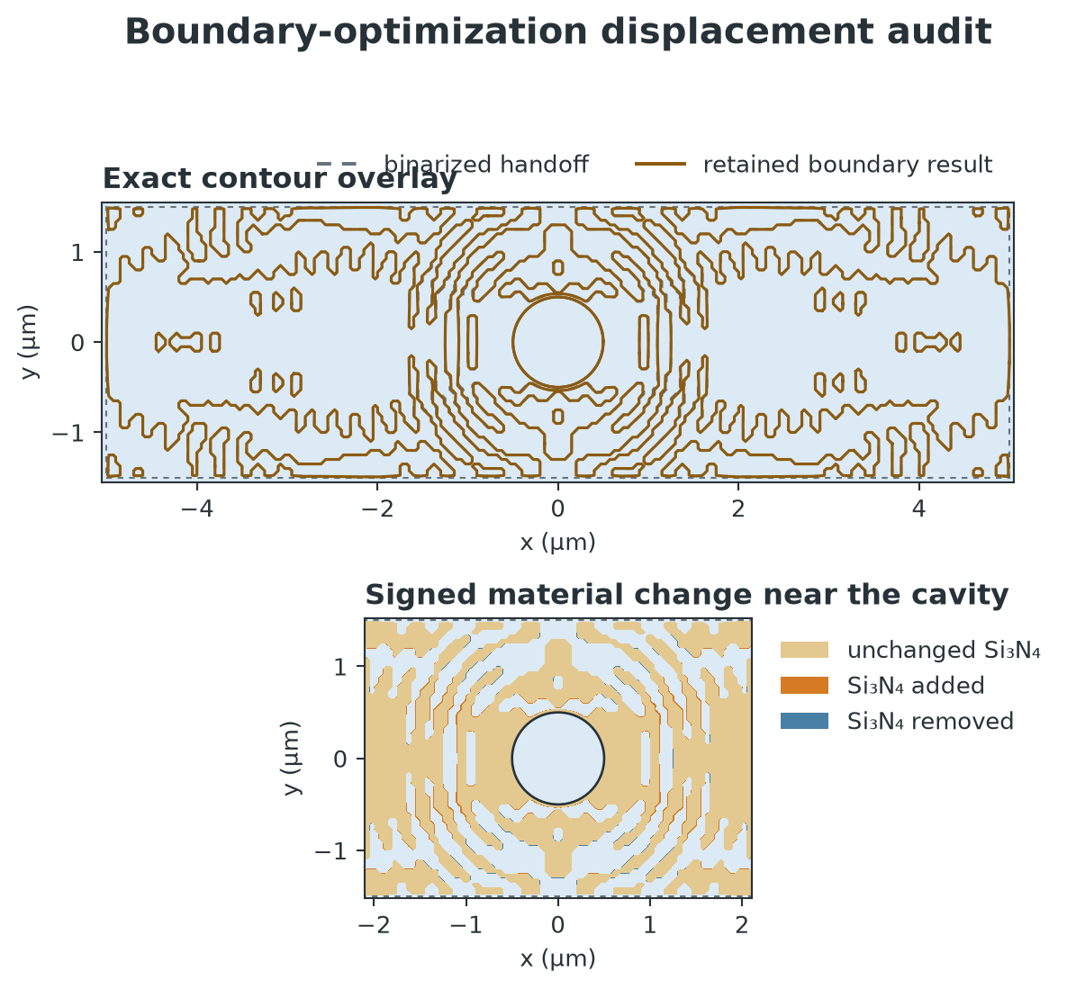
The contour overlay compares the zero-displacement vector decomposition with
the retained candidate_minus_16nm.json. The lower panel rasterizes both exact
GeoJSON geometries at 5 nm spacing so the added and removed Si3N4 slivers are
visible. No changed cell overlaps the protected aperture.
Final geometry cross-sections
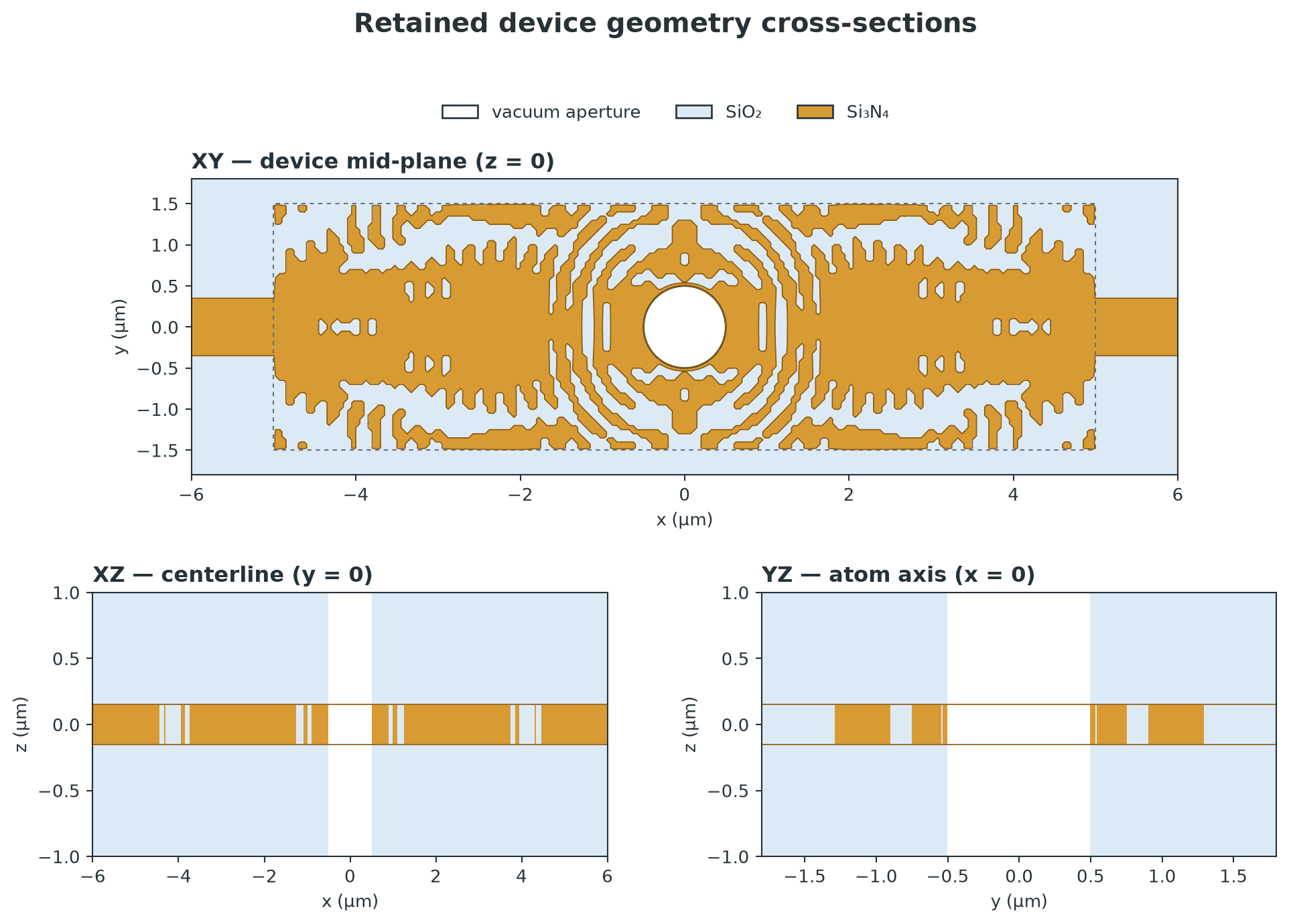
The retained design is a 300 nm Si3N4 layer embedded in SiO2 and connected to 700 nm-wide feedthrough guides. The XZ and YZ views make explicit that the 1 µm-diameter atom opening is a vertical through-cladding vacuum aperture, not merely a hole in the Si3N4 device layer. The dashed XY rectangle is the inverse-design region; the guides outside it are fixed.
Resonant field and spectral evidence
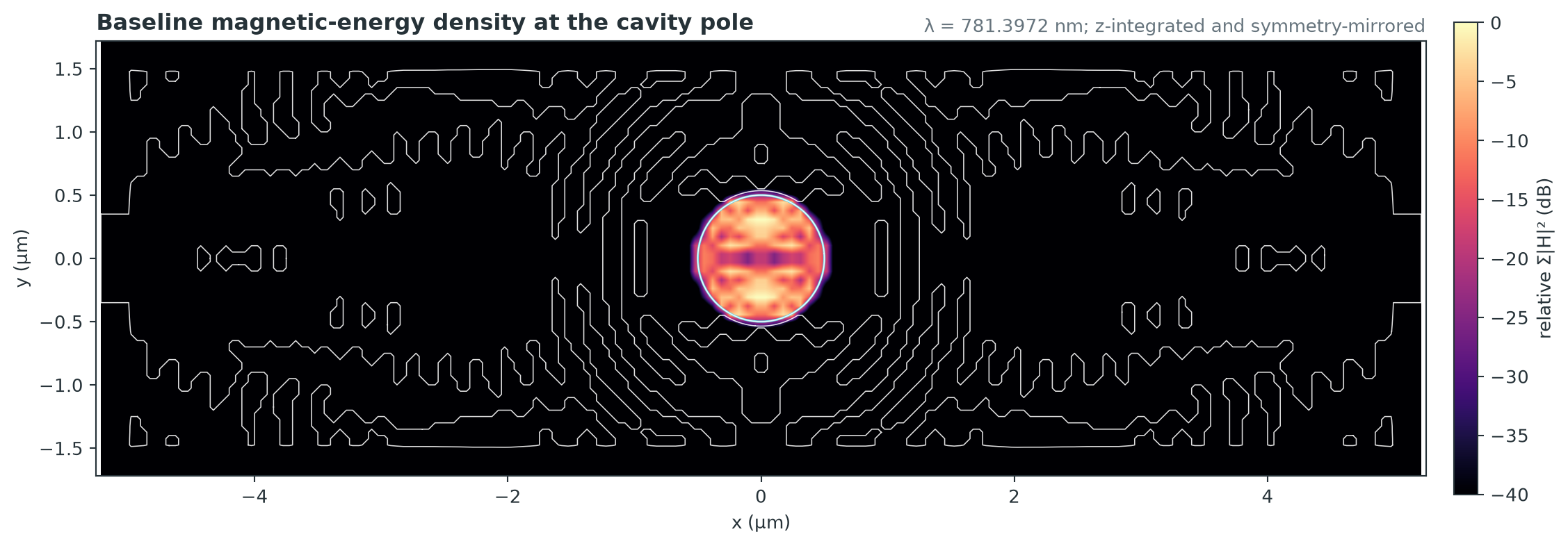
This is the 781.3972 nm point from the retained 61-frequency apodized Tidy3D field monitor. It plots \(10\log_{10}(\sum |H|^2/\max)\), integrates over the positive-z monitor samples, and mirrors the simulated quadrant using the exact field symmetries. The cyan circle marks the protected aperture and the white lines are the binarized baseline contours. Consistent with the numerical energy audit, the view shows why 95.84% of late-time magnetic energy was found inside the 1 µm aperture. This monitor belongs to the binarized baseline; the final 24 ps boundary-candidate certificate did not retain a full-field frequency monitor, so no after-boundary field map is claimed.
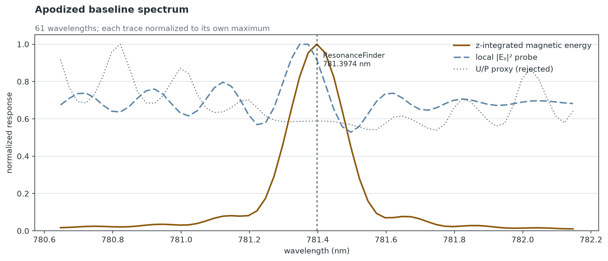
Each 61-point trace is normalized to its own maximum. Magnetic energy peaks at the 781.3974 nm ResonanceFinder pole with a 58.8× peak-to-edge ratio. The stored-energy/outward-flux proxy instead peaks 0.575 nm away, which is why it was rejected as a Q objective. A broadband waveguide-coupling spectrum was not retained by this campaign, so this plot is spectral resonance evidence rather than a claimed coupling spectrum.
Optimization history
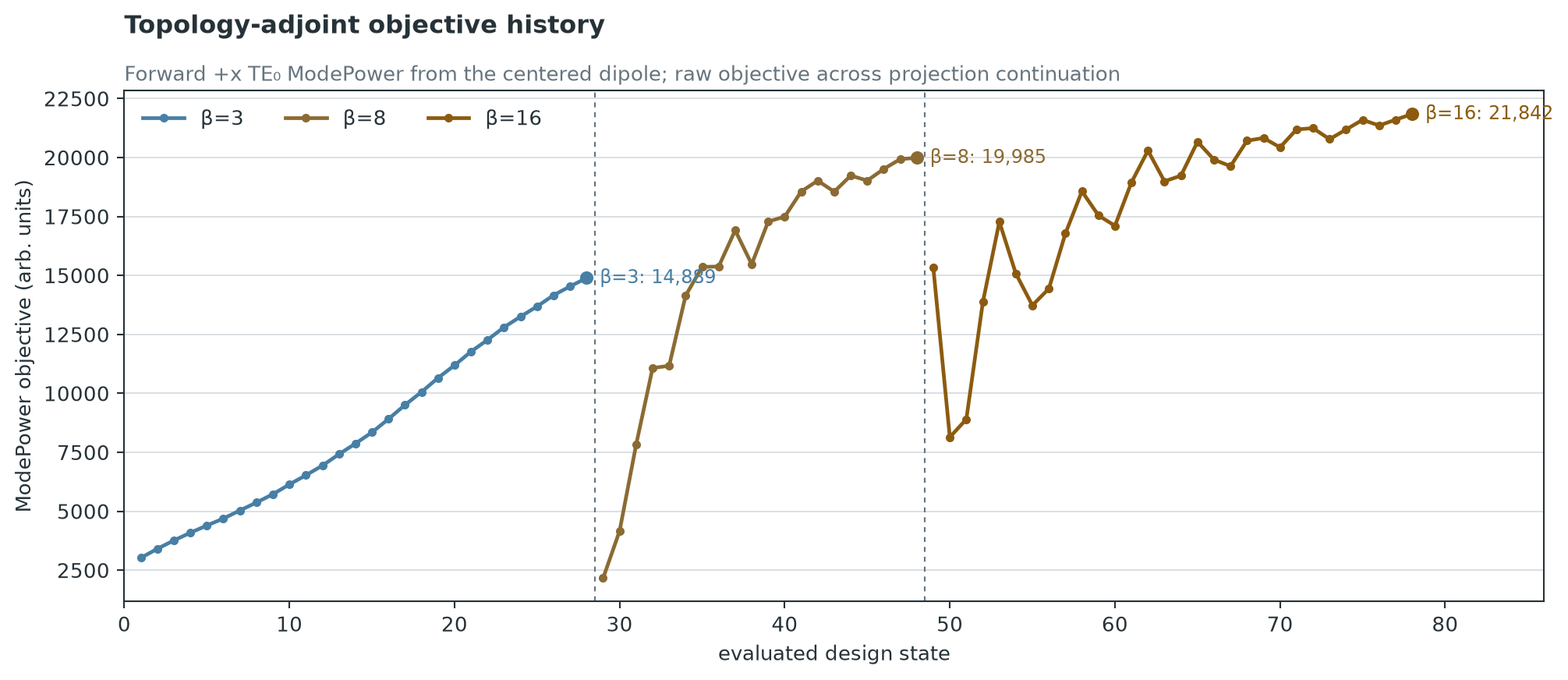
The plotted objective is forward +x TE0 ModePower from the centered dipole. Dashed separators mark changes in projection beta, so discontinuities between stages should not be read as physical regressions. Within the final beta-16 stage the objective rose from 15,321 to 21,842 despite non-monotone Adam steps.
The figures are reproducible with
engines/atom_fishbone_coupler/tools/plot_sin_cavity_full_pipeline.py.
The visual manifest
records the source paths, SHA-256 hashes, chart questions, and plotting
contract for every figure.
What completed
Inverse design and handoff
- 10 × 3 µm Si3N4/SiO2 topology region, 300 nm device layer, symmetric feedthrough guides, and an analytic 1 µm through-vacuum aperture.
- The beta-16 continuation objective increased from 15,321 to 21,842 (+42.6%). The retained topology campaign spent 4.565/12 FlexCredits.
- Binarization and exact contour decomposition produced 51 rings and 3,642 vertices. A 26 × 9 symmetric control field drives 2,898 active vertices; the aperture and design/guide interfaces remain protected.
- Full-domain artifacts are generated by exactly mirroring the positive simulated quadrant. This fixed a small asymmetry caused by independently tessellated mirror contours while preserving the geometry used by Tidy3D's symmetry-reduced solve.
Q measurement was made trustworthy
The original seven-probe layout placed only one probe in the mode. A late-time field audit showed that 95.84% of the resonant magnetic energy lies inside the 1 µm aperture and essentially none lies beyond \(|x|=2\) µm. The Q verifier now uses 12 probes, including ten in or near the aperture, and rejects ResonanceFinder observations whose own estimated error exceeds 2%.
The corrected baseline certificate is:
| geometry | certified median Q | fit range | observation support |
|---|---|---|---|
| binarized inverse design | 7,106 | 6,836–7,366 | 5 probes, 2 combined windows |
| best 12 ps trial (−16 nm survival direction) | 7,294 | 6,837–7,631 | 5 probes, 3 combined windows |
| same trial, 24 ps final | 7,211 | 7,023–7,378 | 2 probes, 3 combined windows |
The apparent 2.6% short-run improvement did not persist as a significant long-run gain.
Objective audit
Three arbitrary-boundary adjoints were executed and checked against fresh ringdowns.
- Stored energy / outward flux: rejected. A 61-frequency sweep had no interior resonance peak before apodization. After late-time apodization, the ratio peaked 0.575 nm away from the ResonanceFinder pole.
- Late-time magnetic energy: the energy spectrum had a strong 58.8× interior peak exactly at the pole, but its boundary gradient remained dominated by excitation/coupling. Opposite ±16 nm directions both produced only small, overlapping Q changes.
- Late/early energy survival: this cancels the common excitation amplitude and is monotonically related to decay for a single mode. Its baseline ratio was 0.1126, corresponding to an approximate single-exponential Q of 8,821. Nevertheless, the ringdown sign test failed: +16 nm gave Q=7,129 while the negative control gave Q=7,294.
The direct continuation along the empirically better negative direction also terminated:
| signed maximum wall move | certified Q |
|---|---|
| 0 nm | 7,106 |
| −16 nm | 7,294 |
| −24 nm | 7,182 |
| −32 nm | 7,202 |
−32 nm is the largest valid move in this direction; −34 nm self-intersects a contour. There is no unresolved ascent toward Q=25,000 on this line.
Budget and resource diagnosis
- Topology: 4.565/12 FlexCredits.
- Boundary/Q stage: 3.917889/4 FlexCredits; 0.082111 remains.
- No RAM blockade was encountered. Exact vector Tidy3D adjoints and 24 ps, 12-probe ringdowns completed normally.
- The failure is not explained by insufficient mesh memory. It is an observability/objective problem combined with an initial mode that is highly localized to the fixed aperture.
What the next campaign should do
The next effort should not spend another adjoint on this 234-variable geometry until a lower-dimensional direct-Q reference exists.
- Re-run the topology stage with an explicit resonant-retention term in addition to dipole-to-guide power. The desired seed should have a mode that extends into movable dielectric rather than placing 95.8% of its magnetic energy in the fixed aperture.
- Parameterize only 8–12 smooth boundary modes in the first 1.5 µm around the aperture. Measure central-difference derivatives with certified ringdowns at steps large enough to exceed the measured Q spread.
- Use those direct derivatives as the reference. Promote an adjoint objective only after its directional cosine and signs agree across at least two geometries and two mesh settings.
- For a claimed Q≥25,000, use a final run of at least 50–60 ps. At 781 nm that Q has a field-amplitude lifetime of about 21 ps, so a 12 ps fit is not a sufficient final certificate.
The retained best geometry is
vector_q_survival_gradient_v1/extended_candidates/candidate_minus_16nm.json.
The final certificate is under
q_evaluations/survival_minus16_mesh35_t24/ in the campaign directory.