Anthracene parallel vertical waveguides
Collection + excitation Si3N4 waveguides normal to the crystal, offset in y; coupling and cross-talk vs. polarization.
Two Si3N4 waveguides are normal to the crystal and propagate along z. The collection guide is centered over an emitter in a 200 nm anthracene film on silver. The excitation guide is displaced by 1.0 um in y.
For each Ex/Ey polarization family:
- a point-dipole simulation measures coupling into both waveguide ports;
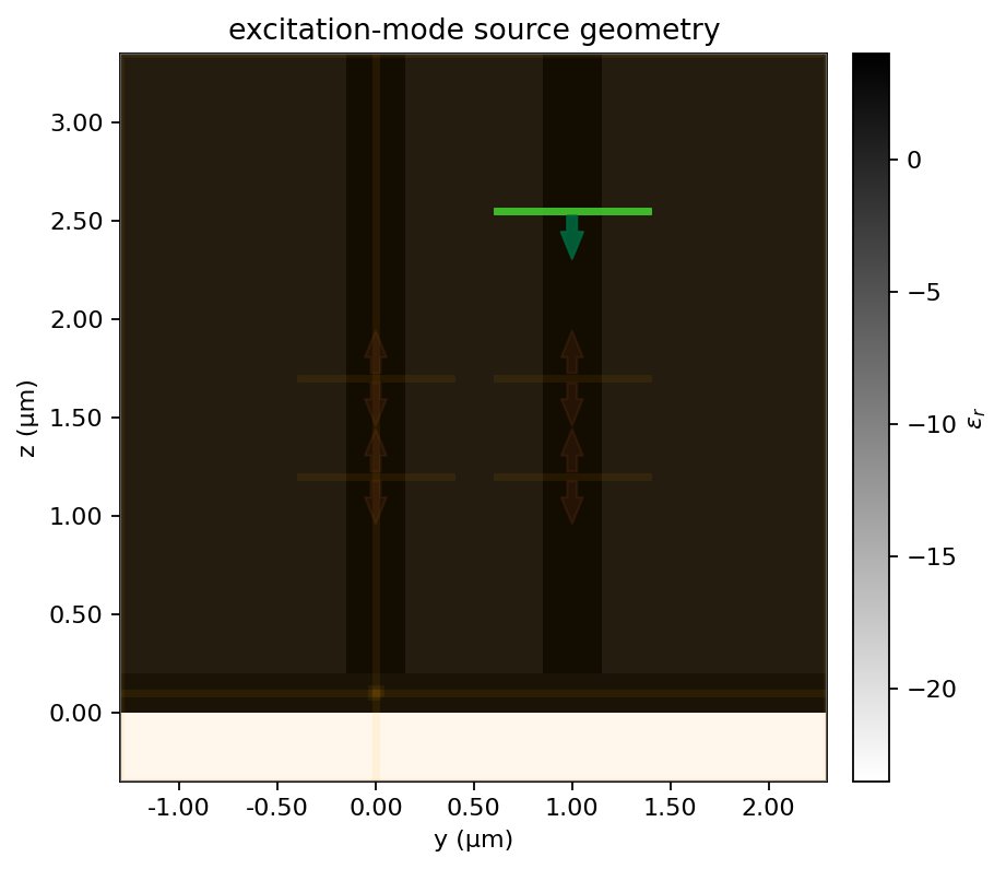
- a unit-power excitation-guide mode is injected with no dipole source and cross-talk into the collection guide is measured.
Both waveguides use exact z-normal Tidy3D mode decomposition at two monitor planes. The duplicate planes provide a built-in port-power consistency check.
python study.py --dry-run
python study.py --estimate
python study.py --run --max-flexcredits 5
python study.py --report
python convergence.py --estimate
python convergence.py --run
The cost guard includes all FlexCredits already billed by the preceding
dual-angle study. The convergence script repeats all four production cases on
a finer mesh and writes data/convergence_metrics.json. The combined HTML
report is at reports/study_report.html.
Results
Anthracene with two parallel vertical waveguides
Technical summary
Eight simulations were completed: Ex- and Ey-oriented dipoles plus Ex- and Ey-like excitation-waveguide inputs, each on the baseline and fine meshes. The fine-mesh results give 43.889% (Ex) and 41.795% (Ey) collection beta into the guide above the emitter. Fine-mesh excitation-to-collection cross-talk is 0.19749% (-27.044 dB) for Ex and 0.074675% (-31.268 dB) for Ey.
Mesh refinement changes collection beta by only 1.2-1.5% and mean cross-talk by 0.08-0.18 dB. The exact cross-talk remains output-plane dependent because the two guides propagate in parallel and behave as a short directional coupler; the report therefore preserves both z-plane values instead of treating the mean as length independent.
Geometry shared by all eight simulations
A 200 nm anthracene film (n=1.8) lies on silver with an emitter at its mid-plane. Two 400 x 300 nm Si3N4 guides in SiO2 are normal to the xy surface and propagate along z. The collection guide is centered over the emitter; the excitation guide is displaced by 1.0 um in +y.
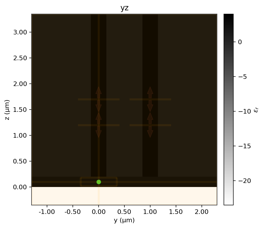
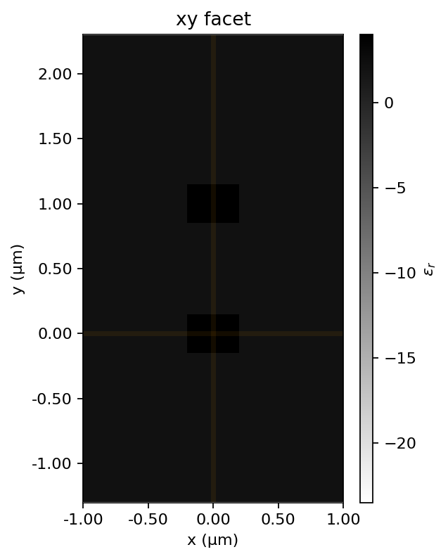
The dipole tests use the point source shown in the first cross-section. The two waveguide-input tests use the z-normal mode-source plane shown below; Ex and Ey differ only by selected mode polarization. The physical structures are otherwise identical for every run.
Simulation matrix and definitions
Four source configurations were run on each of two meshes, for eight completed simulations:
- Ex dipole, no injected mode.
- Ey dipole, no injected mode.
- Unit-power Ex-like excitation-guide mode, no dipole.
- Unit-power Ey-like excitation-guide mode, no dipole.
Dipole beta is matching guided-mode power divided by net outward power through the six-face emitter box. Cross-talk is matching collection-mode power divided by measured incident excitation-mode power. Both ports are evaluated at z=1.20 and 1.70 um. Plane-specific values are reported below; the headline value is the ratio of the mean powers, and relative plane mismatch is |P2-P1|/mean(P1,P2).
Completed simulation coverage
Every row below has its numerical results and both y-z and emitter-plane x-y field plots in this report. Dipole and mode-input geometry figures are shared only where the physical geometry is identical.
| Mesh | Job | Source | Polarization | Geometry evidence | Numerical evidence | Field evidence |
|---|---|---|---|---|---|---|
| Baseline | pvw_Ex_dipole | Point dipole | Ex | Dipole y-z and facet geometry | Dipole coupling, two-plane beta, six-face power | Baseline Ex dipole y-z and x-y |
| Baseline | pvw_Ey_dipole | Point dipole | Ey | Dipole y-z and facet geometry | Dipole coupling, two-plane beta, six-face power | Baseline Ey dipole y-z and x-y |
| Baseline | pvw_Ex_excitation_input | Excitation-guide mode | Ex-like mode 0 | Mode-source y-z geometry | Incident power, cross-talk, reflection, emitter field | Baseline Ex input y-z and x-y |
| Baseline | pvw_Ey_excitation_input | Excitation-guide mode | Ey-like mode 1 | Mode-source y-z geometry | Incident power, cross-talk, reflection, emitter field | Baseline Ey input y-z and x-y |
| Fine | pvw_fine_Ex_dipole | Point dipole | Ex | Fine mesh plus dipole geometry | Fine dipole coupling, two-plane beta, six-face power | Fine Ex dipole y-z and x-y |
| Fine | pvw_fine_Ey_dipole | Point dipole | Ey | Fine mesh plus dipole geometry | Fine dipole coupling, two-plane beta, six-face power | Fine Ey dipole y-z and x-y |
| Fine | pvw_fine_Ex_excitation_input | Excitation-guide mode | Ex-like mode 0 | Fine mesh plus mode-source geometry | Fine incident power, cross-talk, reflection, emitter field | Fine Ex input y-z and x-y |
| Fine | pvw_fine_Ey_excitation_input | Excitation-guide mode | Ey-like mode 1 | Fine mesh plus mode-source geometry | Fine incident power, cross-talk, reflection, emitter field | Fine Ey input y-z and x-y |
Mode identification
| Polarization | Selected mode | Collection n_eff | Excitation n_eff |
|---|---|---|---|
| Ex | 0 | 1.680827 | 1.680827 |
| Ey | 1 | 1.656439 | 1.656439 |
Dipole coupling
| Pol. | Total dipole power | Collection P1 | Collection P2 | Collection beta | Collection orthogonal beta | Excitation P1 | Excitation P2 | Excitation beta | Excitation orthogonal beta |
|---|---|---|---|---|---|---|---|---|---|
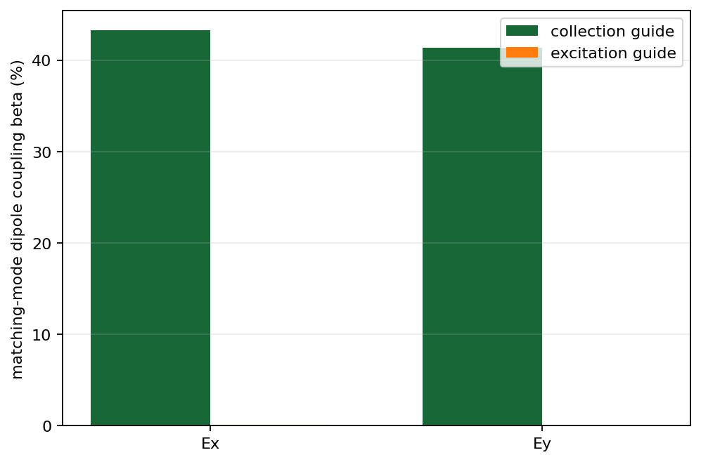
| Ex | 1.718379e+03 | 7.337033e+02 | 7.525206e+02 | 43.245% | 3.1975e-15% | 2.589731e+00 | 1.887500e+00 | 0.13027% | 1.9367e-13% |
| Ey | 1.782328e+03 | 7.253738e+02 | 7.474088e+02 | 41.316% | 2.0147e-14% | 6.457585e-01 | 1.037377e+00 | 0.047217% | 2.9734e-13% |
The collection guide above the emitter captures more than 41% for either dipole orientation, while coupling into the guide displaced by 1 um stays below 0.14%. The chart shows this strong spatial selectivity; exact values remain in the table.
Excitation-guide to collection-guide cross-talk
| Pol. | Incident P1 | Incident P2 | Collection P1 | Collection P2 | Matching cross-talk | Cross-talk dB | Orthogonal conversion | Total guided transfer | Reflection | Collection plane mismatch |
|---|---|---|---|---|---|---|---|---|---|---|
| Ex | 9.817582e-01 | 9.780305e-01 | 2.189988e-03 | 1.749001e-03 | 0.20099% | -26.968 dB | 7.8216e-14% | 0.20099% | 63.219% | 22.391% |
| Ey | 9.671256e-01 | 9.672055e-01 | 7.528977e-04 | 7.520755e-04 | 0.077803% | -31.090 dB | 7.9121e-14% | 0.077803% | 69.85% | 0.109% |
Plane-resolved coupling and cross-talk
These values expose propagation-length sensitivity rather than hiding it in the mean.
| Pol. | Collection beta z=1.20 | Collection beta z=1.70 | Collection mismatch | Excitation beta z=1.20 | Excitation beta z=1.70 | Excitation mismatch | Cross-talk z=1.20 | Cross-talk z=1.70 |
|---|---|---|---|---|---|---|---|---|
| Ex | 42.697% | 43.792% | 2.5322% | 0.15071% | 0.10984% | 31.369% | 0.22307% (-26.516 dB) | 0.17883% (-27.476 dB) |
| Ey | 40.698% | 41.934% | 2.9923% | 0.036231% | 0.058203% | 46.534% | 0.077849% (-31.087 dB) | 0.077758% (-31.093 dB) |
Cross-talk normalization and residual diagnostics
| Pol. | Incident mismatch | Reflection P1 | Reflection P2 | Reflection mismatch | Collection orthogonal P1 | Collection orthogonal P2 | Orthogonal mismatch |
|---|---|---|---|---|---|---|---|
| Ex | 0.38043% | 6.176009e-01 | 6.213488e-01 | 0.60501% | 8.485023e-16 | 6.843696e-16 | 21.415% |
| Ey | 0.0082628% | 6.714975e-01 | 6.796423e-01 | 1.2056% | 7.583992e-16 | 7.720612e-16 | 1.7853% |
The baseline mode-input runs give lower cross-talk for Ey than Ex. Because these bars show the two-plane mean, use the plane-resolved table above when a specific output height or guide length matters.
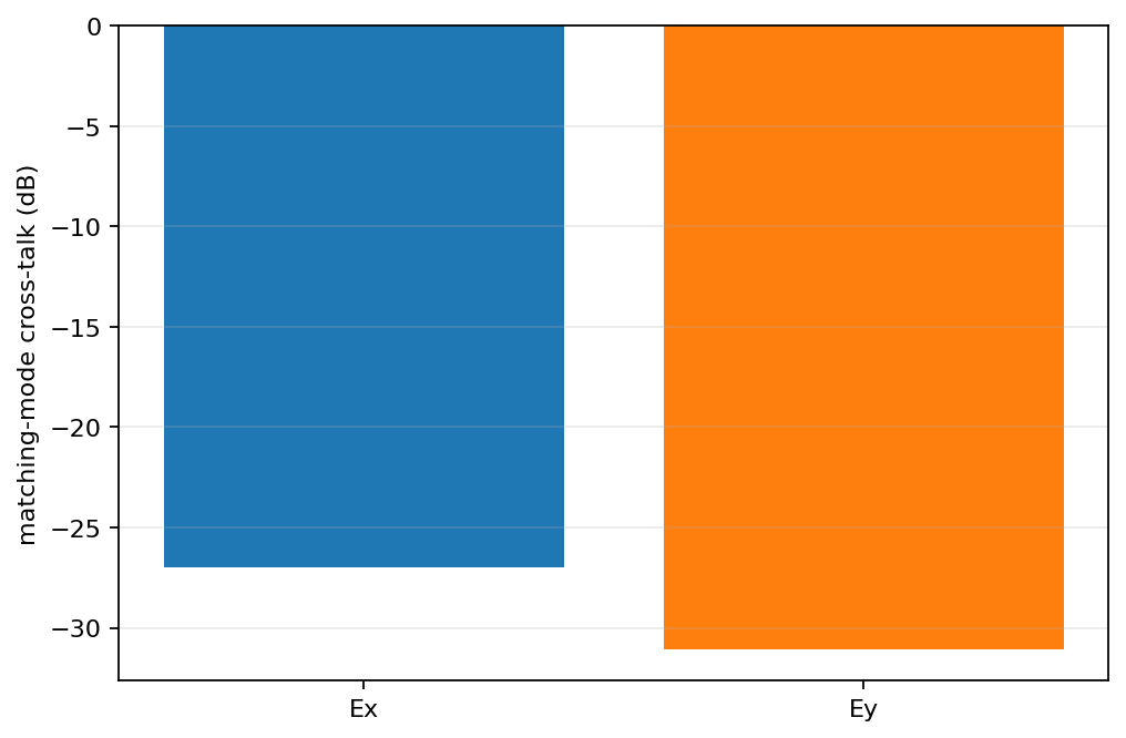
Field at the emitter under excitation-waveguide input
| Input polarization | |Ex| | |Ey| | |Ez| | |E|^2 | |---|---:|---:|---:|---:| | Ex | 5.630213 | 0.034758 | 0.110528 | 31.712726 | | Ey | 0.204895 | 3.044758 | 1.691603 | 12.174057 |
Mesh convergence study
All four simulations were repeated on a systematically finer mesh with identical geometry, sources, monitors, runtime, and normalization.
| Region | Baseline mesh | Fine mesh |
|---|---|---|
| Waveguide region | 25 nm | 20 nm |
| Crystal x/y | 20 nm | 16 nm |
| Crystal z | 12.5 nm | 10 nm |
| Emitter x/y | 10 nm | 8 nm |
| Emitter z | 8 nm | 6 nm |
| Pol. | Collection beta baseline | Collection beta fine | Relative change | Offset-guide beta baseline | Offset-guide beta fine | Relative change | Cross-talk baseline | Cross-talk fine | Change |
|---|---|---|---|---|---|---|---|---|---|
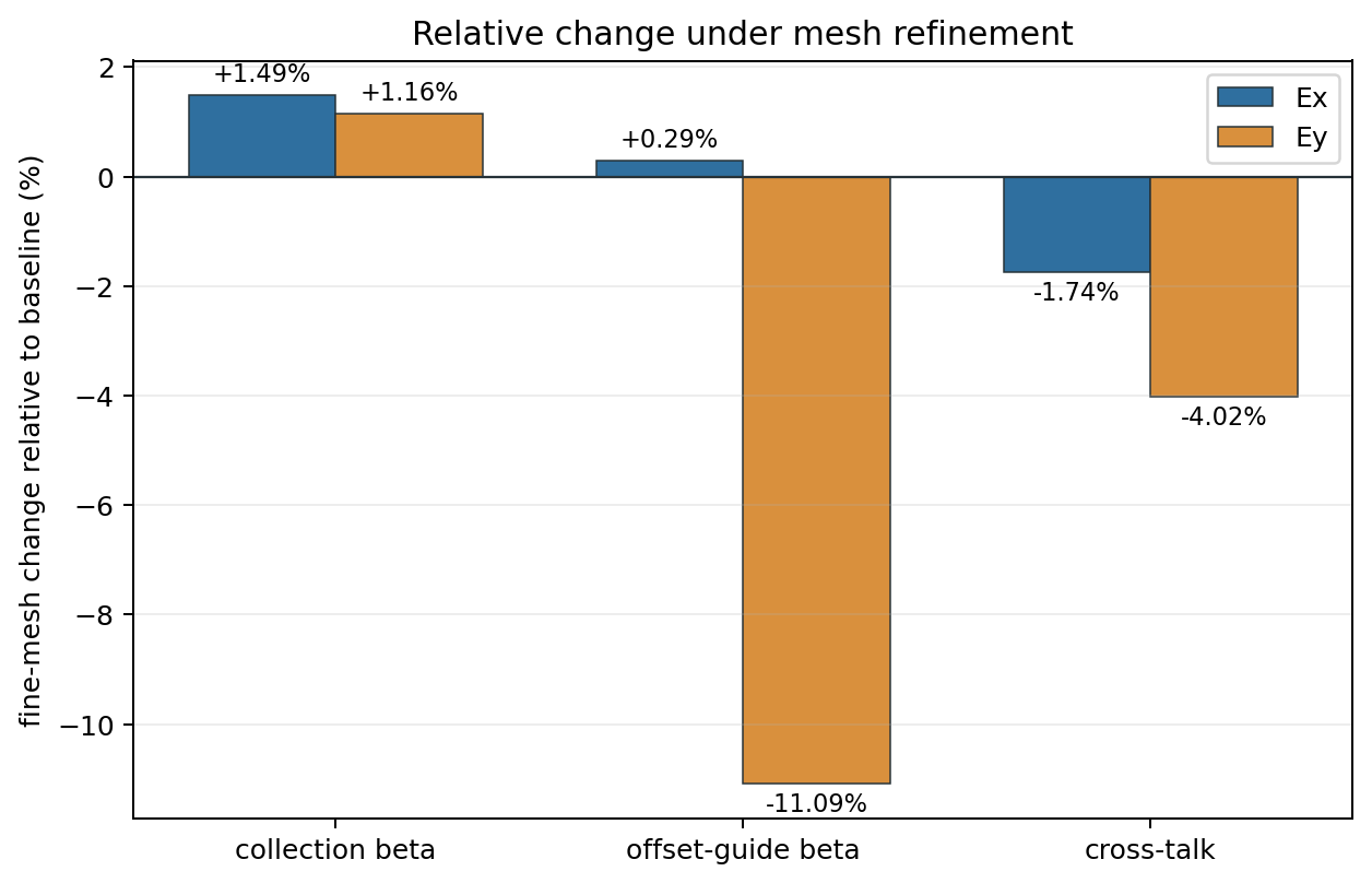
| Ex | 43.245% | 43.889% | +1.490% | 0.13027% | 0.13065% | +0.290% | 0.20099% (-26.968 dB) | 0.19749% (-27.044 dB) | -1.740% (-0.076 dB) |
| Ey | 41.316% | 41.795% | +1.159% | 0.047217% | 0.041983% | -11.085% | 0.077803% (-31.090 dB) | 0.074675% (-31.268 dB) | -4.021% (-0.178 dB) |
Fine-mesh plane-resolved results
| Pol. | Dipole total | Collection beta z=1.20 | Collection beta z=1.70 | Collection beta mean | Offset-guide beta z=1.20 | Offset-guide beta z=1.70 | Offset-guide beta mean | Cross-talk z=1.20 | Cross-talk z=1.70 | Cross-talk mean |
|---|---|---|---|---|---|---|---|---|---|---|
| Ex | 1.703323e+03 | 43.364% | 44.414% | 43.889% | 0.15022% | 0.11108% | 0.13065% | 0.21844% (-26.607 dB) | 0.17647% (-27.533 dB) | 0.19749% (-27.044 dB) |
| Ey | 1.764630e+03 | 41.176% | 42.414% | 41.795% | 0.028624% | 0.055343% | 0.041983% | 0.071753% (-31.442 dB) | 0.077593% (-31.102 dB) | 0.074675% (-31.268 dB) |
The refinement plot shows that the collection beta and mean cross-talk move only a few percent. The larger -11.1% Ey offset-guide change applies to a very small leakage channel and is the least mesh-stable reported beta.
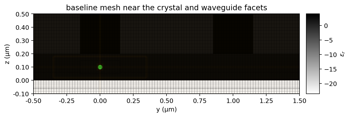
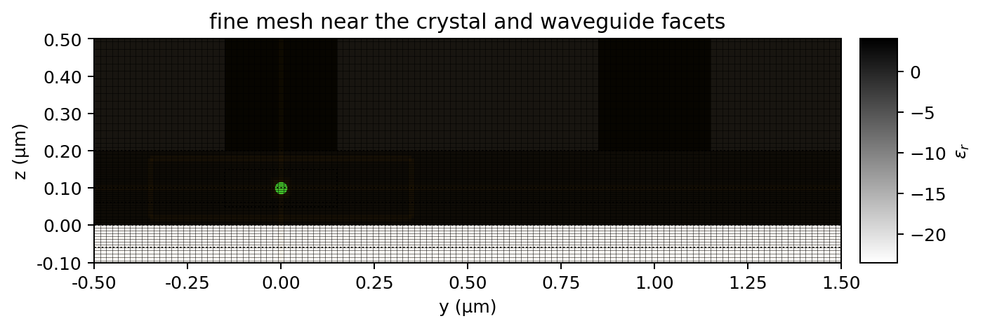
Baseline and fine mesh geometry
The physical geometry is identical in both batches. These enlarged y-z views document the actual discretization around the 200 nm crystal, both waveguide facets, and the silver interface.
Fine-mesh mode identification
| Polarization | Selected mode | Collection n_eff | Excitation n_eff |
|---|---|---|---|
| Ex | 0 | 1.680644 | 1.680644 |
| Ey | 1 | 1.656267 | 1.656267 |
Fine-mesh dipole coupling details
The table preserves raw matching-mode powers at both monitor planes, the mean beta, and the orthogonal-polarization leakage for both guides.
| Pol. | Total dipole power | Collection P1 | Collection P2 | Collection beta | Collection orthogonal beta | Offset-guide P1 | Offset-guide P2 | Offset-guide beta | Offset-guide orthogonal beta |
|---|---|---|---|---|---|---|---|---|---|
| Ex | 1.703323e+03 | 7.386372e+02 | 7.565086e+02 | 43.889% | 2.618e-15% | 2.558784e+00 | 1.892104e+00 | 0.13065% | 7.8029e-14% |
| Ey | 1.764630e+03 | 7.266007e+02 | 7.484509e+02 | 41.795% | 8.6159e-16% | 5.051031e-01 | 9.765932e-01 | 0.041983% | 1.2105e-13% |
Fine-mesh excitation-to-collection cross-talk details
Cross-talk is normalized by the incident matching-mode power measured in the excitation guide. P1 and P2 refer to z=1.20 and 1.70 um.
| Pol. | Incident P1 | Incident P2 | Collection P1 | Collection P2 | Matching cross-talk | Cross-talk dB | Orthogonal conversion | Total guided transfer | Reflection | Collection mismatch |
|---|---|---|---|---|---|---|---|---|---|---|
| Ex | 9.823550e-01 | 9.788037e-01 | 2.145900e-03 | 1.727262e-03 | 0.19749% | -27.044 dB | 4.2535e-14% | 0.19749% | 62.909% | 21.617% |
| Ey | 9.677730e-01 | 9.689326e-01 | 6.944100e-04 | 7.518285e-04 | 0.074675% | -31.268 dB | 4.5687e-14% | 0.074675% | 69.393% | 7.9404% |
Fine-mesh normalization, emitter-field, and residual diagnostics
| Pol. | Incident mismatch | Reflection P1 | Reflection P2 | Reflection mismatch | Orthogonal collection P1 | Orthogonal collection P2 | Orthogonal mismatch | |Ex| at emitter | |Ey| at emitter | |Ez| at emitter | |E|^2 | |---|---:|---:|---:|---:|---:|---:|---:|---:|---:|---:|---:| | Ex | 0.36216% | 6.147733e-01 | 6.189653e-01 | 0.67957% | 4.340196e-16 | 4.001629e-16 | 8.1173% | 5.520082 | 0.031679 | 0.092873 | 30.480929 | | Ey | 0.11974% | 6.673795e-01 | 6.765591e-01 | 1.3661% | 4.161079e-16 | 4.687219e-16 | 11.892% | 0.157201 | 3.046383 | 1.837079 | 12.680020 |
Fine-mesh six-face dipole power budget
| Polarization | x- | x+ | y- | y+ | z- | z+ |
|---|---|---|---|---|---|---|
| Ex | 5.393115e+01 | 5.393101e+01 | 9.617221e+01 | 9.571137e+01 | 6.245218e+01 | 1.341125e+03 |
| Ey | 8.954815e+01 | 8.954851e+01 | 5.286282e+01 | 5.227798e+01 | 5.821270e+01 | 1.422179e+03 |
Fine-mesh field maps for all four source configurations
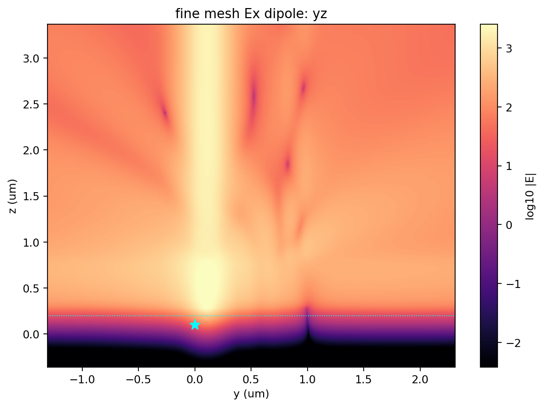
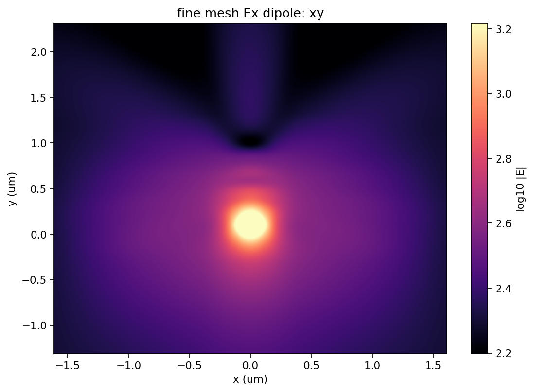
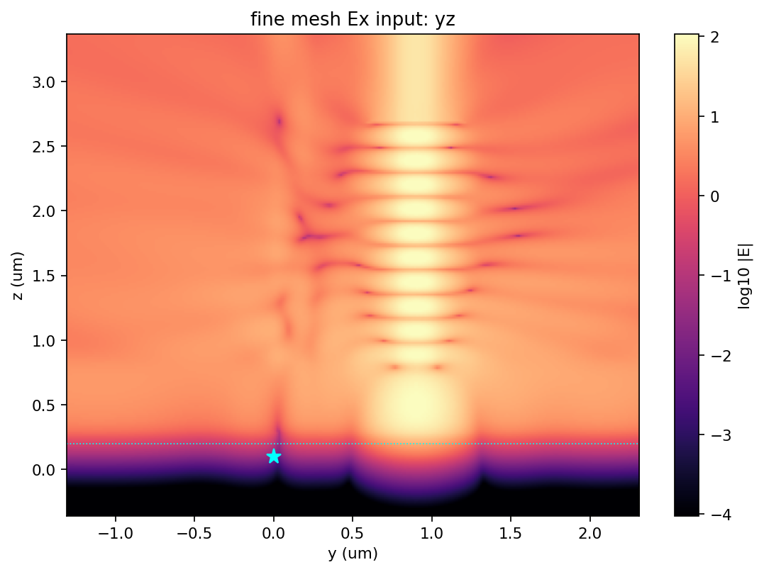
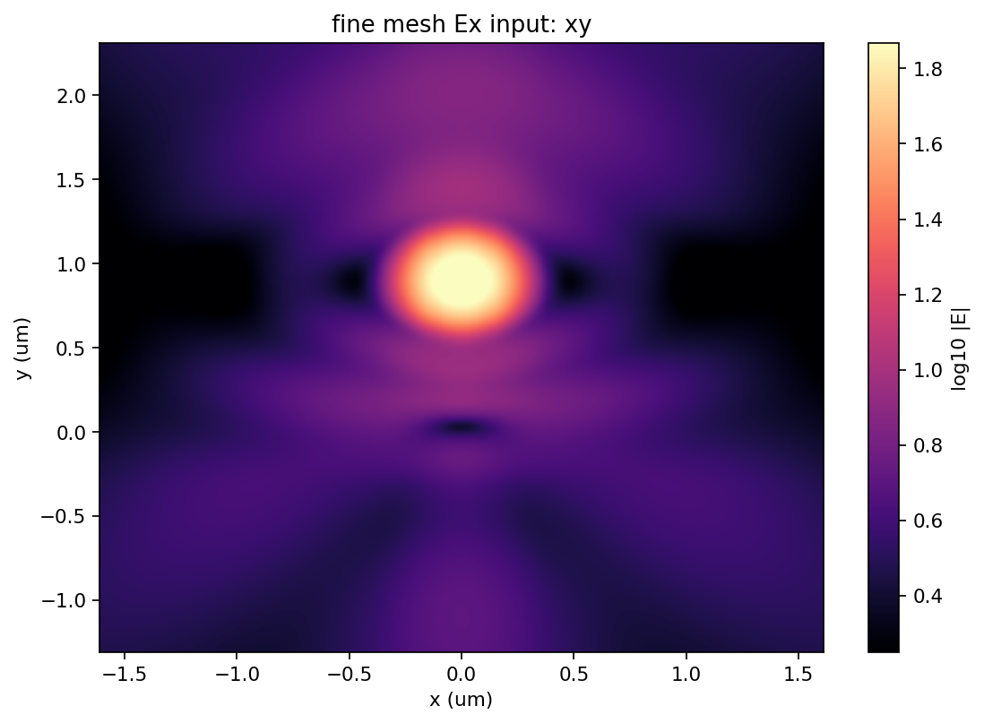
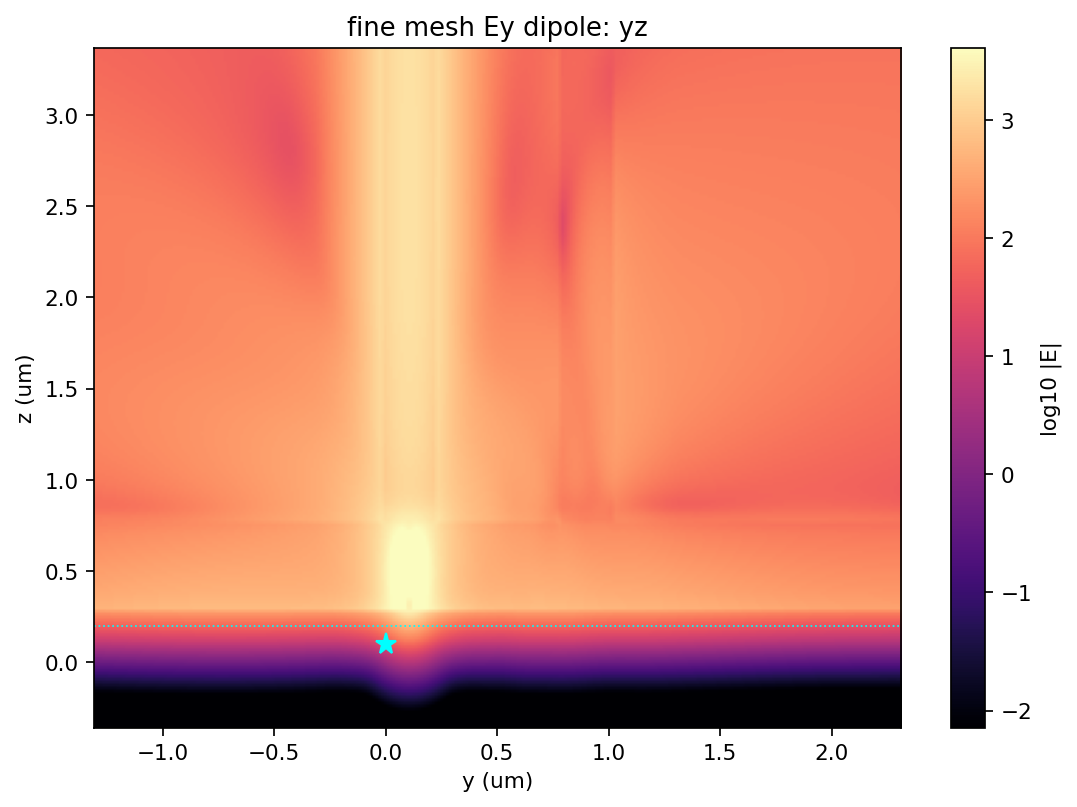
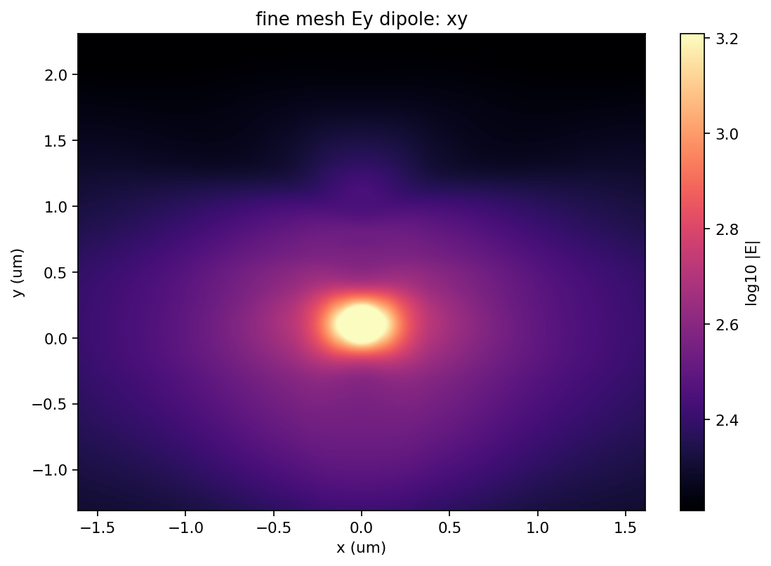
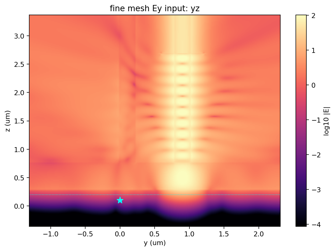
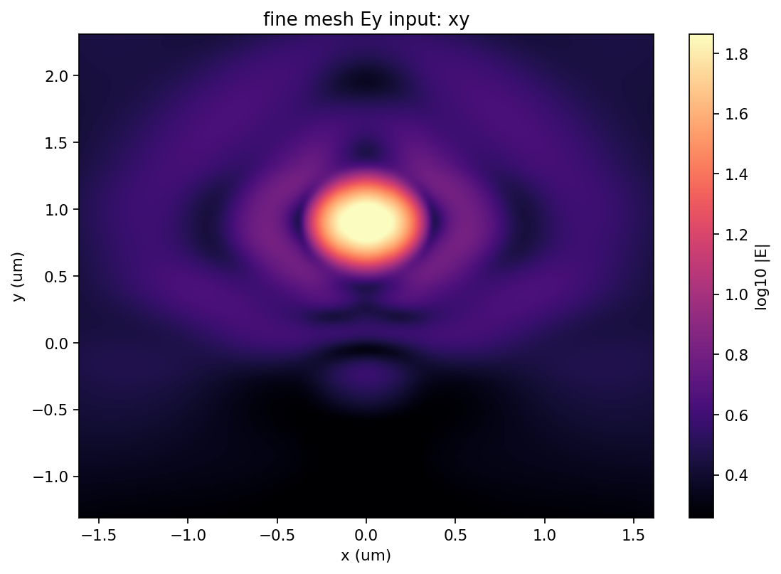
These plots are generated from the four fine-mesh HDF5 results, not reused from the baseline. The y-z and emitter-plane x-y views use the same plotting definitions as the baseline figures for direct comparison.
Fine mesh: Ex dipole
The dipole-source maps show radiation launched at the crystal mid-plane and preferential capture by the guide directly above the emitter.
Fine mesh: Ex excitation-mode input
The input-source maps show the driven excitation guide, the field reaching the emitter location, and the much weaker field admitted to the collection guide.
Fine mesh: Ey dipole
The dipole-source maps show radiation launched at the crystal mid-plane and preferential capture by the guide directly above the emitter.
Fine mesh: Ey excitation-mode input
The input-source maps show the driven excitation guide, the field reaching the emitter location, and the much weaker field admitted to the collection guide.
Baseline-mesh field maps
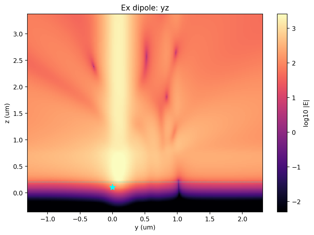
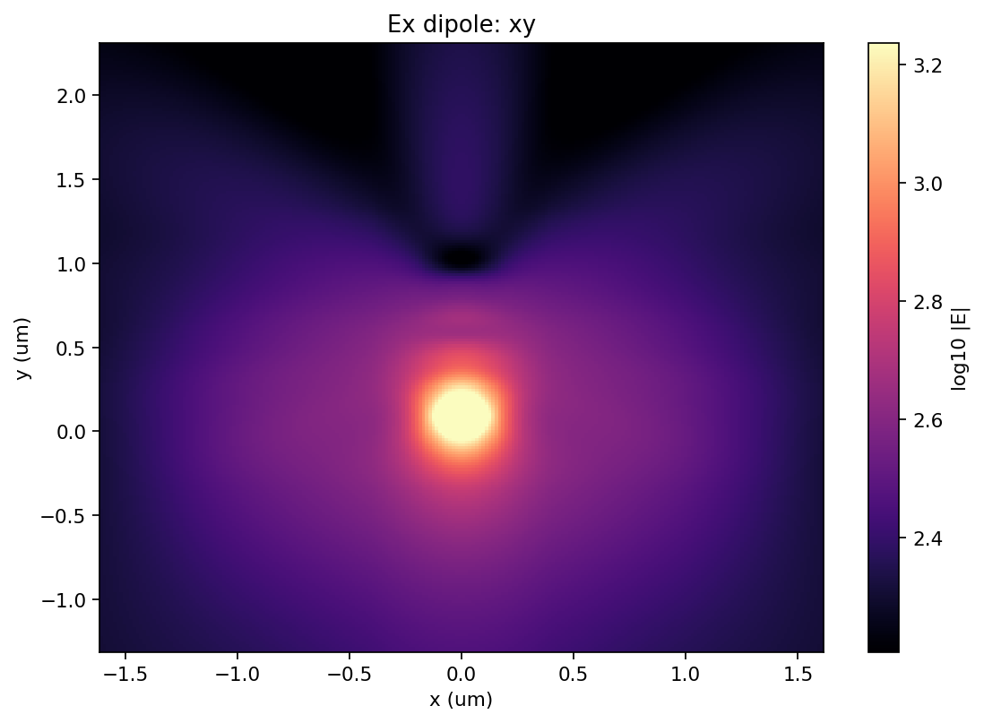
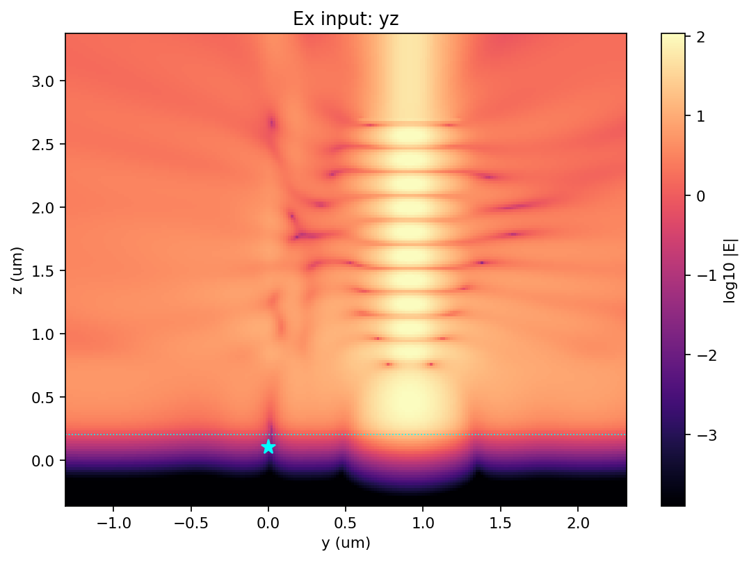
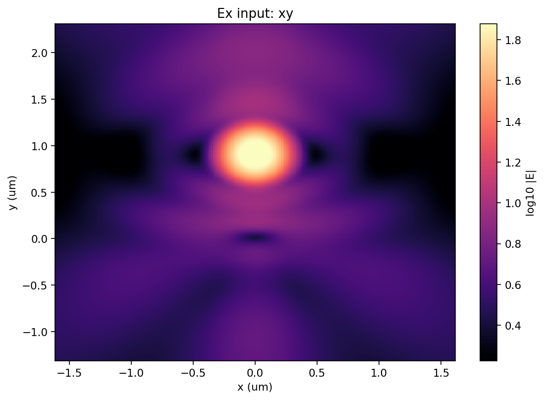
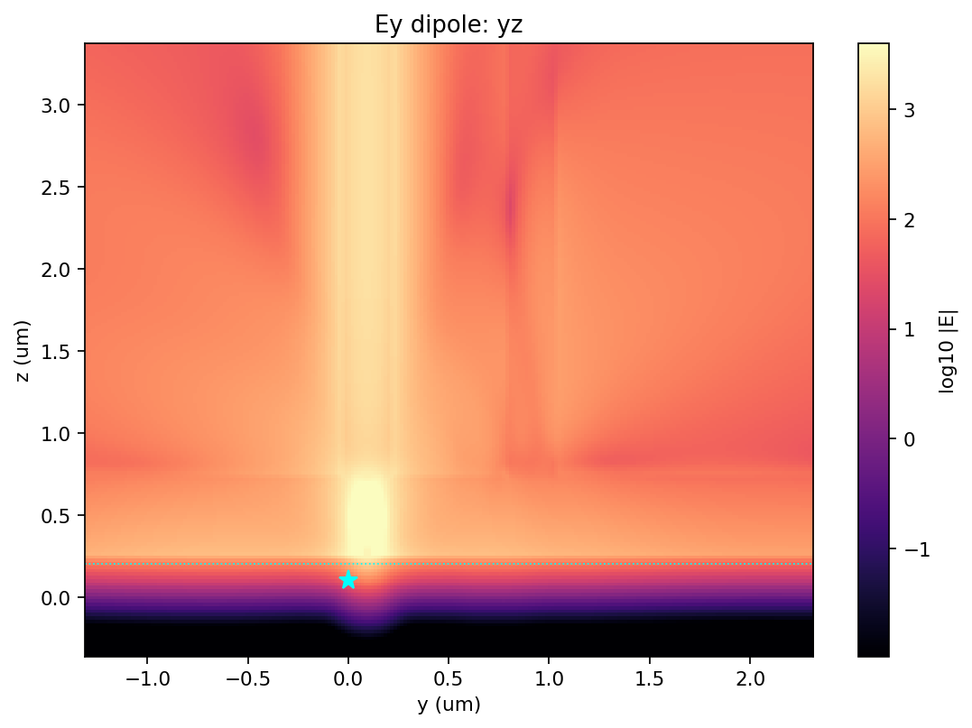
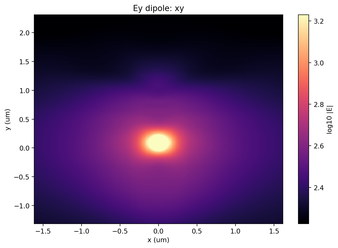
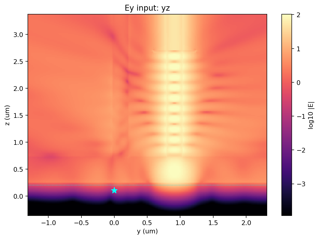
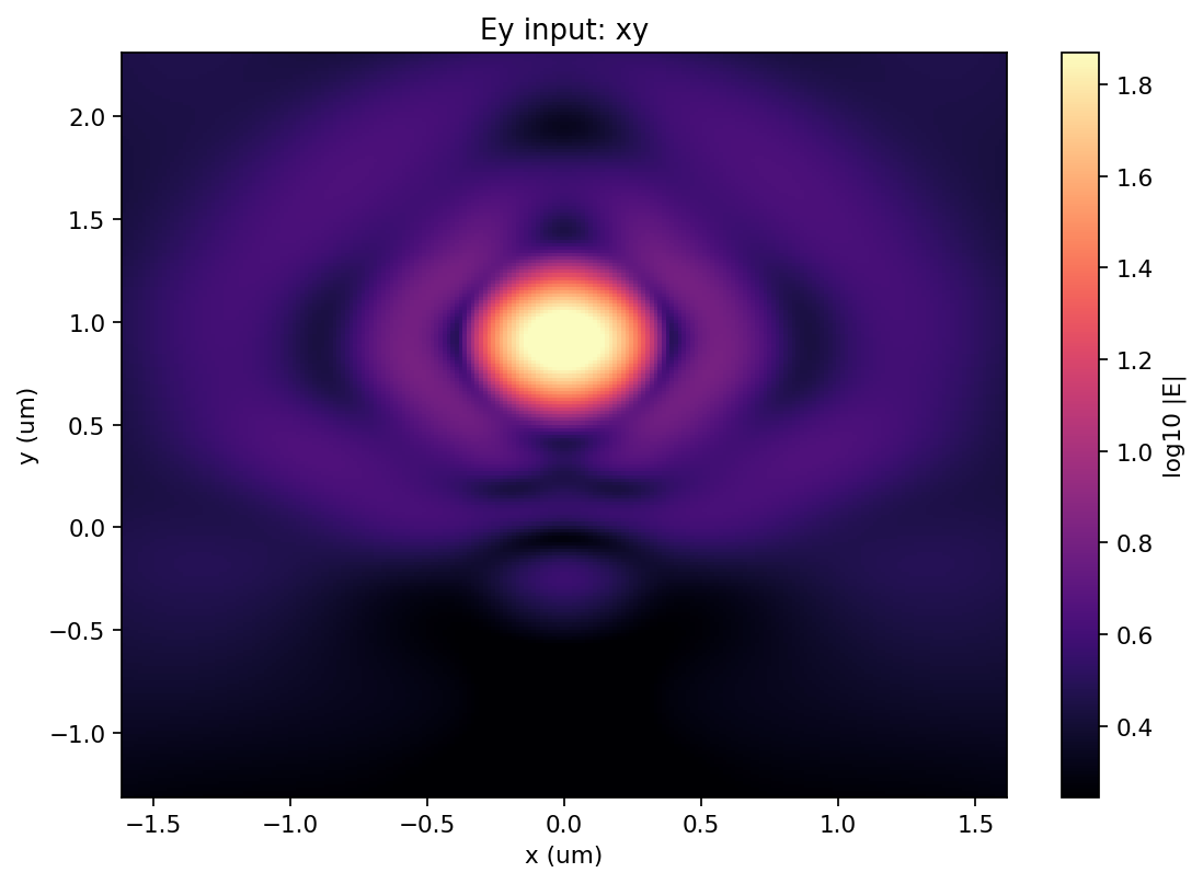
These field maps document every baseline source configuration. Each y-z map shows propagation through both vertical guides and the crystal interface; each x-y map shows the field distribution in the emitter plane.
Baseline mesh: Ex dipole
The dipole maps show emission from the crystal mid-plane and the dominant upward field captured by the collection guide; compare the weak field around the guide displaced by 1 um.
Baseline mesh: Ex excitation-mode input
The mode-input maps show the excitation guide driven downward toward the crystal, the field at the emitter, and the smaller field transferred to the collection guide.
Baseline mesh: Ey dipole
The dipole maps show emission from the crystal mid-plane and the dominant upward field captured by the collection guide; compare the weak field around the guide displaced by 1 um.
Baseline mesh: Ey excitation-mode input
The mode-input maps show the excitation guide driven downward toward the crystal, the field at the emitter, and the smaller field transferred to the collection guide.
Per-face dipole power budget
| Polarization | x- | x+ | y- | y+ | z- | z+ |
|---|---|---|---|---|---|---|
| Ex | 5.710545e+01 | 5.710495e+01 | 9.948864e+01 | 9.936545e+01 | 6.706456e+01 | 1.338250e+03 |
| Ey | 9.184294e+01 | 9.184348e+01 | 5.675381e+01 | 5.664566e+01 | 6.260855e+01 | 1.422634e+03 |
Cost
- Prior studies billed: 1.3817 FC.
- Baseline batch estimate / actual: 1.3204 / 0.1538 FC.
- Fine-mesh batch estimate / actual: 3.3415 / 0.3341 FC.
- Current study actual including convergence: 0.4880 FC.
- Cumulative actual: 1.8696 FC of the authorized 5.0 FC.
| Mesh | Job | Task ID | Status | Cells | Estimated FC | Billed FC |
|---|---|---|---|---|---|---|
| baseline | pvw_Ex_dipole | fdve-d03ef0ce-fecc-4e7a-ac01-a33de605a1fe | complete | 11,789,631 | 0.3282 | 0.0339 |
| baseline | pvw_Ex_excitation_input | fdve-87fe24b2-6987-49a4-a5fc-0ca5dc2e463f | complete | 11,789,631 | 0.3320 | 0.0430 |
| baseline | pvw_Ey_dipole | fdve-08864cc7-4790-440e-9467-b0cd62603426 | complete | 11,789,631 | 0.3282 | 0.0339 |
| baseline | pvw_Ey_excitation_input | fdve-1f4b596a-ec5a-4af9-907b-667f0f17aa51 | complete | 11,789,631 | 0.3320 | 0.0430 |
| fine | pvw_fine_Ex_dipole | fdve-a685a0f4-32d6-4020-81f3-7deac5c11fb5 | complete | 23,733,556 | 0.8334 | 0.0833 |
| fine | pvw_fine_Ex_excitation_input | fdve-7d1d7c35-67ab-4b39-8a32-047b86893a96 | complete | 23,733,556 | 0.8373 | 0.0837 |
| fine | pvw_fine_Ey_dipole | fdve-88b82e84-065a-430b-a1db-e7c1c2535a34 | complete | 23,733,556 | 0.8334 | 0.0833 |
| fine | pvw_fine_Ey_excitation_input | fdve-5f215747-26ae-4750-8c47-e468b346a434 | complete | 23,733,556 | 0.8373 | 0.0837 |
Numerical confidence and limitations
- Both ports use exact mode decomposition, unlike the angled-port aperture approximation in the preceding study.
- Two z-separated modal planes provide an internal propagation consistency check. Collection-guide dipole beta changes by 2.53% (Ex) and 2.99% (Ey).
- Ex cross-talk changes by 22.39% between the two planes, while Ey changes by 0.109%. Because the guides remain parallel, local-guide power is propagation-length dependent; the two plane-specific values are more defensible than treating the mean as a universal device number.
- Fine-mesh reruns changed collection beta by +1.49% (Ex) and +1.16% (Ey), and mean cross-talk by -0.076 dB and -0.178 dB. These headline quantities are mesh-converged to a few percent at the tested refinement.
- The very weak Ey dipole coupling into the offset guide changed by -11.1% under refinement; treat that small leakage beta as lower confidence.
- The fine mesh does not remove plane dependence (fine Ex cross-talk plane mismatch is 21.62%). This supports the interpretation that propagation length / coupled-guide beating, rather than mesh alone, controls the exact port-plane value.
- Domain-size, port-window, and propagation-length sweeps were not performed. Cross-talk must therefore be quoted at a specified z plane or guide length, not as a universal length-independent property.
- Results are monochromatic at 780 nm and assume an ideal planar cleave, isotropic anthracene, smooth interfaces, and the specified laboratory-frame dipole axes.
Recommended next steps
- Specify the physical parallel-guide interaction length and place the reported output port at that height; cross-talk is not length independent.
- If the design decision depends on sub-0.1 dB accuracy, sweep domain size and port-window size in addition to the completed mesh refinement.
- Use the fine-mesh Ex and Ey values as the current design estimates, while retaining both plane-specific values as the propagation-length bracket.
Further questions
- What cleaved-guide length will exist above the crystal before the two guides separate or terminate?
- Should excitation efficiency be optimized by the local field intensity at the emitter, by absorbed molecular power, or by a saturation-rate model?
Complete machine-readable values: data/metrics.json and data/convergence_metrics.json.
Downloads
FDTD simulation study only -- no GDS/STL deliverable files exist in this tree.
Source: nanophotonic_devices/emitter_coupling/anthracene_parallel_vertical_waveguides_v1/