Fiber sheath v1
Passive self-aligning Nanoscribe fiber sheath that drops onto an on-chip lens.
A Nanoscribe (IP-S) test structure for a passive, self-aligning fiber sheath that drops onto an on-chip lens. The fiber gets pushed into the sheath, lands on three index-matching bumps, and is held against the lens with a small air gap underneath. Optical glue is later applied; the bumps keep the fiber from sitting on a stray particle and the membrane keeps the glue off the lens.
                              ___________
                            /             \         <- funnel  (15..345 deg)
                           |               |           ID 124 -> 250, wall 20 um
                           |               |           height 50 um
                            \             /
                            +-------------+
                            |   fiber     |        <- sheath top (15..345 deg)
                            |   (125 OD)  |           ID 124, OD 250
                            |             |           height 750 um
                            |             |
                            +-------------+
                            |             |        <- sheath bottom
                            |             |           ID 130, OD 250
                            |             |           height 50 um
                            +-------------+
       . . . o . . . . . . . o . . . . . . . o   <- 3 bumps (r=50, hemi r=3)
       =============================================  <- membrane (2 um, OD 250)
       |xxx|     |xxx|     |xxx|     |xxx|     |xxx|  <- base ring segments
       |xxx|     |xxx|     |xxx|     |xxx|     |xxx|     0..60, 120..180, 240..300
       ___________ /\ ____________                       ID 75, OD 250, h ~ 8 um
                  /  \ <- lens (Cartesian-oval aspheric, apex 5 um)
       ============================================  <- PEC (substrate / mirror)
       z = 0
Files
generate_geometry.py— designs the lens and emits 3 STL files +geometry_params.json+lens_profile.npz.simulate_optics.py— runs a Tidy3D FDTD simulation of the lens + membrane + fiber + PEC stack and writes a fresh timestamped report inreports/.stl/region1_lens_core.stl— high-resolution writing region.r ≤ 75 um,z ∈ [-0.5, 13] um. Contains the lens, the inner part of the 3-segment base ring, the inner part of the membrane, and the three bumps.stl/region2_inner_sheath.stl— no-stitching writing region.r ≤ 75 um,z ≥ 13 um. Contains the inner wall of the sheath bore (where the fiber lives).stl/region3_outer_support.stl— bulk support infrastructure. Everything outsider = 75 umfor allz.
The split is sized to the ~150 um Nanoscribe writing field. Write order on the tool: region 1 first (highest resolution, the lens), region 2 second (no stitching across the optical bore), region 3 last (support that may be stitched freely).
Geometry parameters (microns / degrees)
| part | parameter | value |
|---|---|---|
| Lens | apex height | 7.0 |
| Lens | shape | aplanatic hyperboloid (K = −n², R = h_apex·(n−1)) |
| Lens | outer radius (design) | ≈ 10.6 |
| Lens | gap above the apex | 3.0 |
| Lens | apparent fiber face (in air) | ≈ 13.31 |
| Base ring | inner / outer diameter | 75 / 250 |
| Base ring | height | 10.0 |
| Base ring | arc segments | 0–60°, 120–180°, 240–300° |
| Membrane | thickness | 2.0 |
| Membrane | outer diameter | 250 |
| Bumps | hemisphere radius | 3.0 |
| Bumps | orbit radius / angles | 50 / 30°, 150°, 270° |
| Sheath gap | angular | 30° (sheath spans 15–345°) |
| Sheath bottom | ID / OD / height | 130 / 250 / 50 |
| Sheath top | ID / OD / height | 124 / 250 / 750 |
| Funnel | ID (bottom → top) | 124 → 250 |
| Funnel | wall thickness / height | 20 / 50 |
| Total height | top of funnel above PEC | 860 |
Indices (780 nm): IP-S resin n = 1.51, air n = 1.0. Fiber is Thorlabs 630HP
at 780 nm: 125 µm clad, 3.5 µm core, NA = 0.12 (n_core 1.4583, n_clad 1.4533),
MFD ≈ 5.4 µm. (Change FIBER_CORE_RADIUS_UM, N_FIBER_CORE, N_FIBER_CLAD
in generate_geometry.py to target a different fiber.)
The sheath slit spans 15°–45° in azimuth (a 30° gap), so the tube wall covers 45°–375° (i.e. wraps past 0°). The gap sits directly over the 0°–60° base-ring spoke for mechanical support.
Running it
# from this directory
pip install trimesh manifold3d scipy tidy3d

python generate_geometry.py     # -> stl/*.stl, geometry_params.json, lens_profile.npz
python simulate_optics.py       # -> reports/report_YYYYMMDD_HHMMSS.md + figures/
simulate_optics.py submits one FDTD job to the Tidy3D cloud per invocation.
Each run writes a fresh report_<timestamp>.md — re-runs never overwrite a
prior report. Override knobs via environment variables:
| variable | default | meaning |
|---|---|---|
SHEATH_WL0 |
1.550 | center wavelength (um) |
SHEATH_BW |
0.1 | spectral bandwidth (um) |
SHEATH_NWL |
41 | number of wavelength samples |
SHEATH_MIN_STEPS |
14 | minimum grid cells per wavelength |
SHEATH_RUN_TIME |
6e-13 | FDTD run time, seconds |
SHEATH_SIMXY |
30.0 | transverse FDTD window (um) |
SHEATH_FIBLEN |
15.0 | fiber stub length above the face (um) |
SHEATH_NOTES |
"" | free-form notes appended to the report |
Lens design
generate_geometry.py ships two lens design families and selects one with the
module-level LENS_DESIGN constant.
Hyperboloid (default). An aplanatic conic surface with conic constant
K = −n² and vertex radius R = h_apex·(n−1), sized so that the back focal
point lands exactly on the PEC at z = 0:
z(r) = h_apex − sag(r),
sag(r) = (r²/R) / (1 + √(1 − (1+K)(r/R)²))
This focuses collimated light from above (in air) stigmatically to a point
inside the resin. The fiber beam at the lens position is very close to
collimated (Rayleigh range ≫ propagation distance), so this is a good
approximation. The lens extends out to where sag(r) = h_apex (lens skirt
meets the PEC plane), capped at LENS_R_CAP = 14 um to stay inside the
scaffold ID with margin. At h_apex = 7 um, r_max ≈ 10.6 um — large enough
to cover the full SMF-28 mode.
Cartesian oval (alternate). The unique surface that is stigmatic between
the virtual fiber face (its paraxial image after the resin slab,
z_v = 8 + 5/1.51 = 11.31 um) and a focus on the PEC. The oval condition is
n_air · √(r² + (z_v − z_s)²) + n_resin · √(r² + z_s²) = K
K = n_air (z_v − h_apex) + n_resin · h_apex
For this very compact geometry the natural oval extent is small (r_max ≈ 2 um
at h_apex = 5 um), so it under-fills the beam aperture and the lens edge
behaves as a diffractive obstacle. Useful as a comparison case.
The chosen profile is numerically tabulated and saved to lens_profile.npz
for use by the simulator.
Simulation scope
FDTD is expensive, so the simulation only covers the optical core, not the 800 um sheath. The simulated stack is
z ≤ 0                : PEC
z = 0 .. 5           : resin lens (Cartesian oval, revolved)
z = 5 .. 8           : air gap
z = 8 .. 10          : resin membrane
z = 10 .. 13         : resin / index-matching glue
z = 13 ..            : SMF-28-like fiber (core + cladding)
The bumps live at r = 50 um (well outside the FDTD window) so they are implicit — the 3 um zone between membrane and fiber face is modeled as a uniform resin layer (the glue + bump composite).
A fundamental HE11 mode source is launched downward from inside the fiber. A mode monitor at the same plane records the returned amplitude in the +z direction. Coupling efficiency is
CE(f) = |amps('+', mode_index=0, f)|²
(the source is normalized to unit launched modal power).
Results
First preflight (baseline)
Sheath v1 — Optical Simulation Report
- Generated:
2026-05-27T11:57:36 - Wavelength range: 1.520 – 1.580 um (31 points)
- Center wavelength: 1.550 um
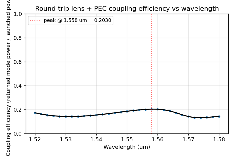
- Peak coupling efficiency: 0.2030 at 1.558 um
- Mean coupling over the band: 0.1625
1. Structure geometry
The full Nanoscribe build is the chip-to-fiber sheath described in
README.md. Critical z-levels (in microns above the PEC substrate):
| level | z (um) |
|---|---|
| PEC substrate (and lens base) | 0.00 |
| Lens apex | 5.000 |
| Top of 3-segment base ring | 8.00 |
| Top of membrane | 10.00 |
| Top of bumps / fiber face | 13.00 |
| Sheath top end | 810.0 |
| Funnel top | 860.0 |
Material indices: resin (IP-S) n = 1.51, fiber core n = 1.4504, fiber cladding n = 1.4447.
2. Lens design
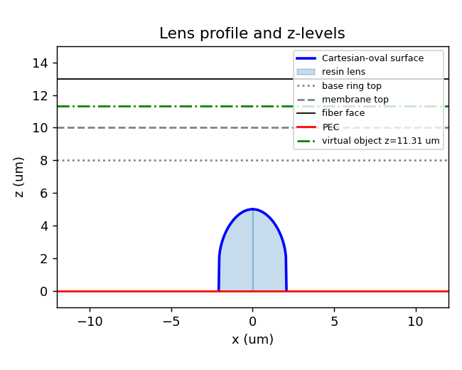
The lens is a Cartesian-oval refractive surface designed to image the fiber face stigmatically onto the PEC plane. The air–resin interface height z_s® satisfies
$$ n_{air} \sqrt{r^2 + (z_v - z_s)^2} + n_{resin} \sqrt{r^2 + z_s^2} = K, $$
where the virtual object position is
$$ z_v = z_{mem,bot} + (z_{fiber} - z_{mem,bot}) / n_{resin} = 11.311 \text{ um}, $$
and K is set by the on-axis ray: K = n_air (z_v − h_apex) + n_resin h_apex.
- Apex height h_apex = 5.000 um (chosen below the 8 um base ring height to leave a 3.00 um air gap under the membrane)
- Outer radius r_max = 2.078 um (where the surface meets z = 0)
- Effective NA in air = sin(arctan(r_max / (z_v − h_apex))) ≈ 0.313
3. Simulation domain
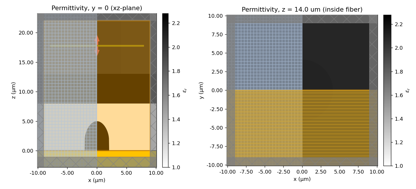
- Transverse window: 18.00 × 18.00 um
- Vertical extent: z ∈ [-1.08, 22.09] um
- Grid: auto with 11 cells per wavelength at λ₀
- Boundary conditions: PML in x, y, z; PEC structure at z ≤ 0
- Symmetry: (1, −1, 0) — Ex-polarized HE11 mode
- Run time: 0.35 ps
Source plane (ModeSource, '−z' direction) at z = 17.80 um. ModeMonitor at the same plane collects the returned ('+z') amplitude.
4. Fiber mode
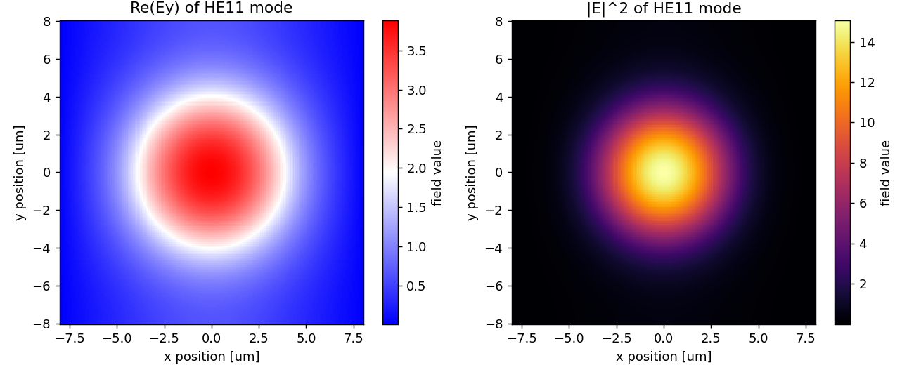
Step-index SMF-28-like fiber (core radius 4.1 um, n_core 1.4504, n_clad 1.4447). The mode solver finds the fundamental HE11; the source injects mode 0 with unit modal power.
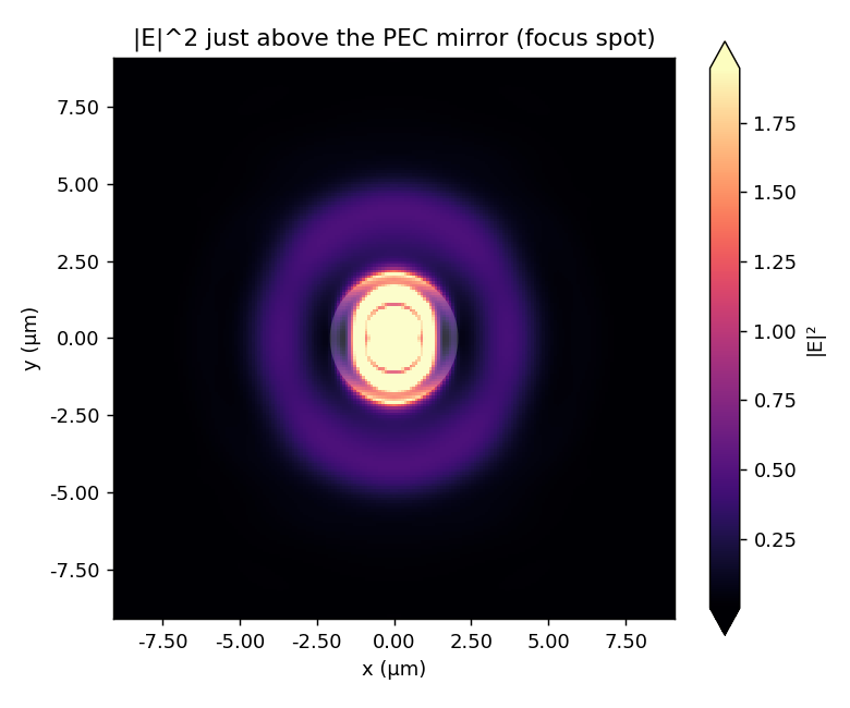
5. FDTD field
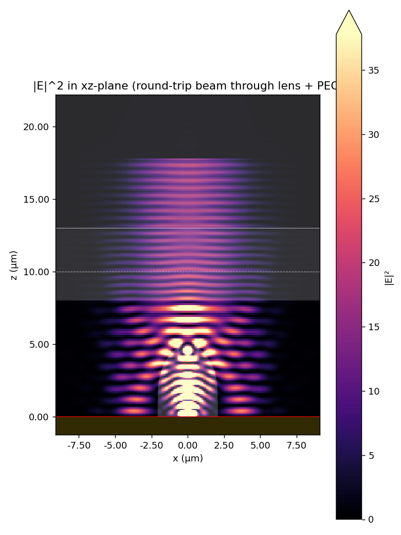
The launched mode propagates down through the cladding, glue layer, membrane, air gap, and Cartesian-oval lens. The PEC at z = 0 reflects the converging wavefront, which retraces back up through the lens and recouples into the fiber mode.
6. Round-trip coupling efficiency
Coupling efficiency is computed from the mode monitor amplitudes as
CE(f) = |amps('+', mode_index=0, f)|^2
which, given the unit-power ModeSource normalization, is the fraction of launched power that returns into the fiber's fundamental mode.
Numerical summary
- Peak: CE = 0.2030 at λ = 1.558 um
- Mean over band: 0.1625
- Min over band: 0.1309
Raw data
- Coupling efficiency CSV:
figures/20260527_115627_coupling.csv - Geometry parameters:
../geometry_params.json - Lens profile (npz):
../lens_profile.npz - STL files:
../stl/
Final report
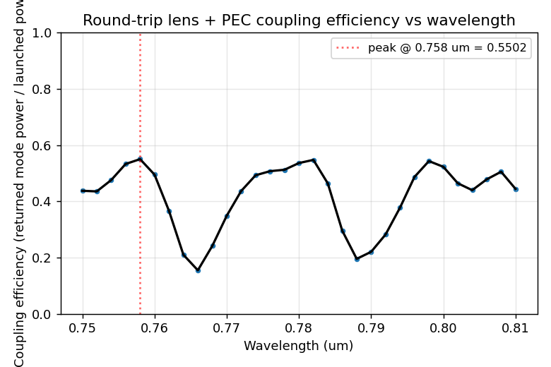
Sheath v1 — Optical Simulation Report
- Generated:
2026-05-27T12:31:31 - Wavelength range: 0.750 – 0.810 um (31 points)
- Center wavelength: 0.780 um
- Peak coupling efficiency: 0.5502 at 0.758 um
- Mean coupling over the band: 0.4195
1. Structure geometry
The full Nanoscribe build is the chip-to-fiber sheath described in
README.md. Critical z-levels (in microns above the PEC substrate):
| level | z (um) |
|---|---|
| PEC substrate (and lens base) | 0.00 |
| Lens apex | 7.000 |
| Top of 3-segment base ring | 10.00 |
| Top of membrane | 12.00 |
| Top of bumps / fiber face | 15.00 |
| Sheath top end | 812.0 |
| Funnel top | 862.0 |
Material indices: resin (IP-S) n = 1.51, fiber core n = 1.4583, fiber cladding n = 1.4533.
2. Lens design
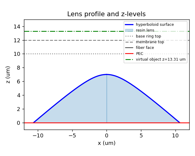
Design family: hyperboloid. Aplanatic hyperboloid (K = -n^2, R = h_apex (n-1)) — collimated air -> point focus at PEC inside resin.
For the hyperboloid (default), the air-side surface follows the aplanatic conic
$$ z® = h_{apex} - \dfrac{r^2 / R}{1 + \sqrt{1 - (1 + K)(r/R)^2}}, \qquad K = -n_{resin}^2, \quad R = h_{apex} (n_{resin} - 1), $$
so collimated light from above is focused stigmatically onto the PEC at z = 0 inside the resin.
Paraxial reference: viewed through the 5.0 um resin layer above the lens, the fiber face appears at
$$ z_v = z_{mem,bot} + (z_{fiber} - z_{mem,bot}) / n_{resin} = 13.311 \text{ um}. $$
- Apex height h_apex = 7.000 um (chosen below the 10.0 um base ring to leave a 3.00 um air gap under the membrane)
- Outer radius r_max = 10.616 um (where the surface meets z = 0, capped at LENS_R_CAP from
generate_geometry.py) - Effective NA in air ≈ 0.860
3. Simulation domain
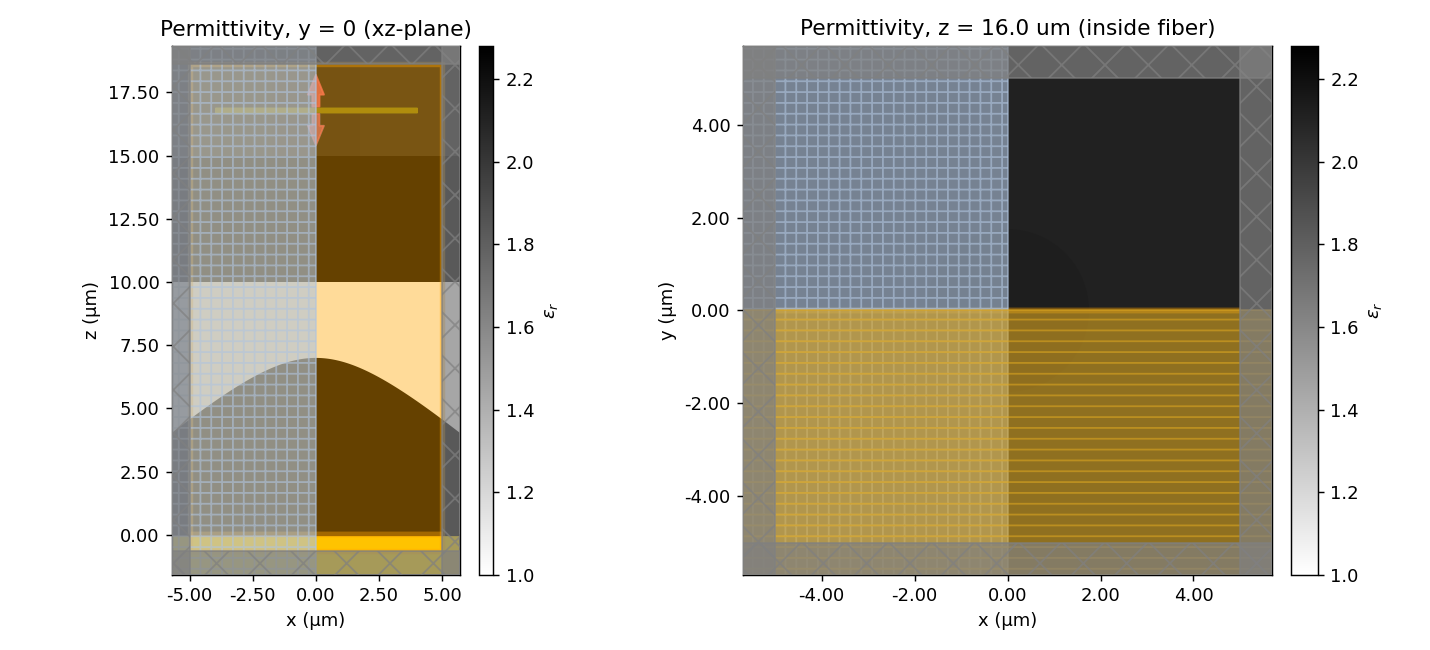
- Transverse window: 10.00 × 10.00 um
- Vertical extent: z ∈ [-0.62, 18.62] um
- Grid: auto with 9 cells per wavelength at λ₀
- Boundary conditions: PML in x, y, z; PEC structure at z ≤ 0
- Symmetry: (1, −1, 0) — Ey-polarized HE11 mode
- Run time: 0.60 ps
Tidy3D cloud cost
- Pre-run estimate: 0.0250 FlexCredits
- Actual cost: nan FlexCredits
Source plane (ModeSource, '−z' direction) at z = 16.80 um. ModeMonitor at the same plane collects the returned ('+z') amplitude.
4. Fiber mode
Step-index fiber model (core radius 1.75 um, n_core 1.4583, n_clad 1.4533, design wavelength 780 nm). The mode solver finds the fundamental HE11; the source injects mode 0 with unit modal power.
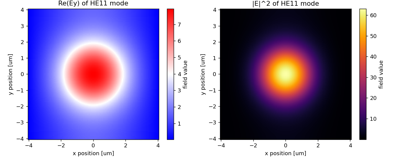
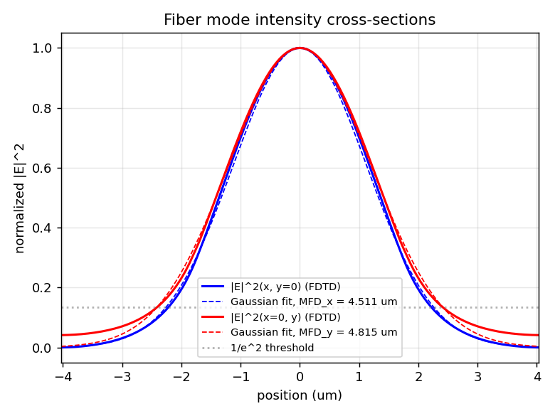
Measured mode-field diameter (MFD)
The MFD is computed four ways from the FDTD-solved mode at the source plane so it can be compared directly to fiber datasheets:
| definition | value (um) |
|---|---|
| Gaussian fit, x-cut ( | E |
| Gaussian fit, y-cut ( | E |
| 2nd-moment (D4σ of | E |
| Petermann II (coupling-relevant) | 5.039 |
Reference fibers @ 780 nm: HI780 ≈ 5.0 µm, 630HP ≈ 4.4 µm, SM800 ≈ 5.6 µm.
For 630HP coupling, the simulated MFD should land near 4.4 µm — if not,
change FIBER_CORE_RADIUS_UM / N_FIBER_CORE / N_FIBER_CLAD in
generate_geometry.py and re-run.
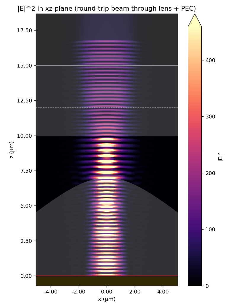
5. FDTD field
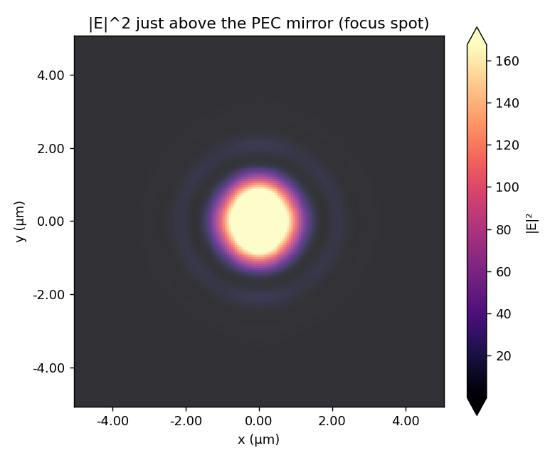
The launched mode propagates down through the cladding, glue layer, membrane, air gap, and Cartesian-oval lens. The PEC at z = 0 reflects the converging wavefront, which retraces back up through the lens and recouples into the fiber mode.
6. Round-trip coupling efficiency
Coupling efficiency is computed from the mode monitor amplitudes as
CE(f) = |amps('+', mode_index=0, f)|^2
which, given the unit-power ModeSource normalization, is the fraction of launched power that returns into the fiber's fundamental mode.
Numerical summary
- Peak: CE = 0.5502 at λ = 0.758 um
- Mean over band: 0.4195
- Min over band: 0.1548
Raw data
- Coupling efficiency CSV:
figures/20260527_122912_coupling.csv - Geometry parameters:
../geometry_params.json - Lens profile (npz):
../lens_profile.npz - STL files:
../stl/
Downloads
Source: nanophotonic_devices/fiber_collection_optics/sheath_v1/