
Axisymmetric cosine atom-hole optimizer#
Live research campaign · spectral pole-acquisition stage
This is a true rotational-symmetry reduction of the m=0 TM Maxwell equations, not a 3-D voxel optimization and not a Cartesian wedge. A z dipole sits at the center of an air cylinder constrained to remain at least 1.000 µm in diameter. A finite-interval DCT decodes global cosine coefficients into one radial SiN etch line, which is filtered, projected, and swept through 2π. Its SiN thickness and the shared top/bottom SiO₂-cladding thickness are differentiable scalar design variables. The full physical radius is present from the start; spatial frequencies unlock progressively rather than introducing new radial shells.
Geometry: from one line to a fabricable 3-D body#
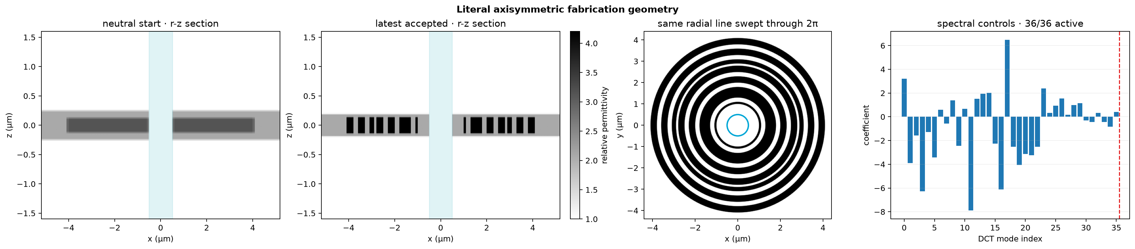
The cyan region is the hard air-hole constraint. The current geometry audit
reports air_hole_clear=True, outside_design_air=True,
and single_etch_extrusion=True. The discovery grid
contains only 36 global cosine
coefficients and three dimensions on a 208 ×
129 r-z field grid. The 36 decoded fabrication samples
are not independent optimization variables. Rotating the line creates the
complete 3-D device; there are no angular sectors or voxels.
Target-frequency field#
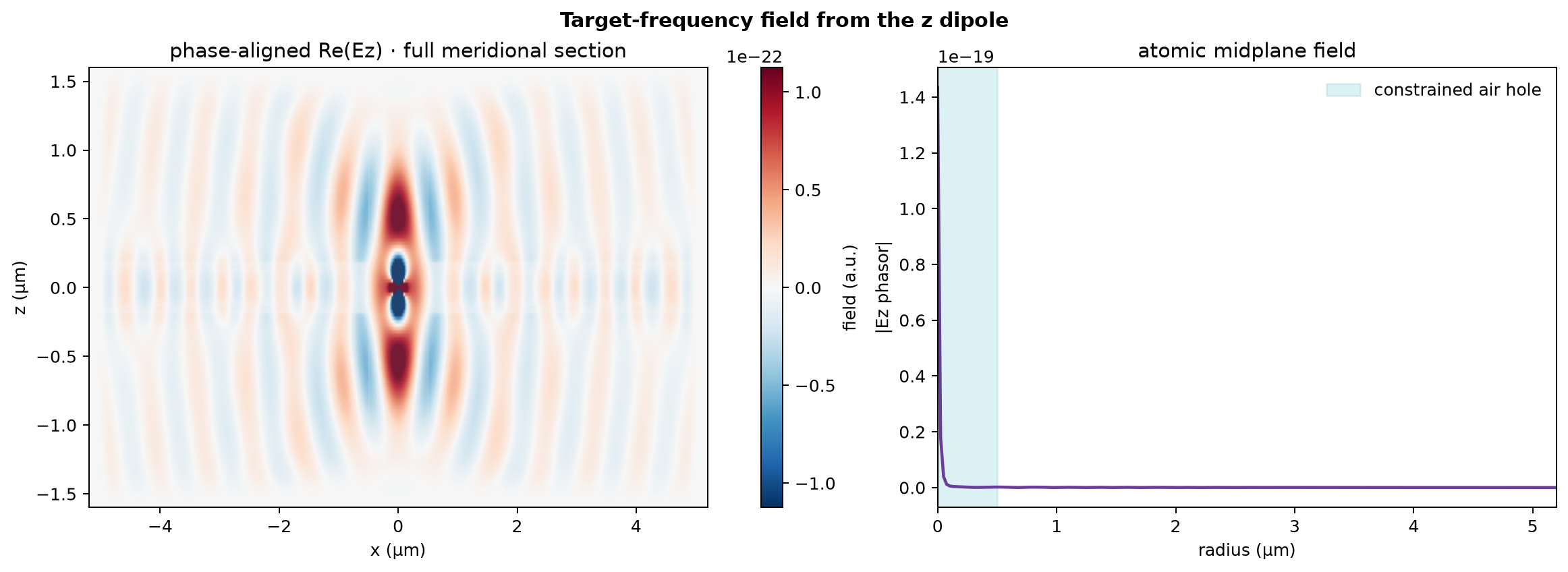
The displayed field is the literal complex target-frequency FDTD phasor. Its left half is reconstructed from rotational symmetry only for visualization; it was not simulated independently.
Optimization and automatic pole gate#
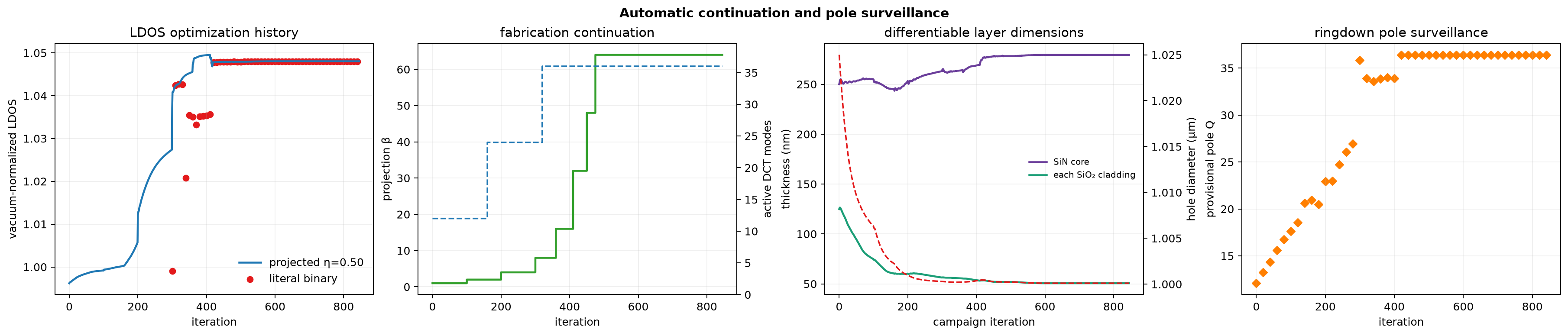
The campaign is a cold zero-coefficient start, decoding to a neutral 50% density line; no V8 geometry or optimizer moment is inherited. The lowest 12 DCT modes are active through iteration 159, 24 through iteration 319, and all 36 thereafter. β rises from 1 to 64 over 475 updates and reaches the fully projected stage around iteration 500. Smooth worst-case optimization over η=0.45, 0.50, and 0.55 begins at β=32. The cosine block uses one shared RMS normalization so coefficient steps retain their Maxwell-gradient amplitude ratios; the three physical dimensions retain independent Adam scaling.
Every 20 updates, a separate 180-period forward ringdown fits both the atomic field and total electromagnetic energy. Handoff requires all three morphology projections to be fully projected and to satisfy conservative Q≥40, field residual ≤10%, energy residual ≤12%, field/energy Q agreement within 1.5×, bounded decay-window variation, and ≤3% detuning. The shifted stage uses a memory-safe 100-period differentiable tape to maximize robust fitted Q/V with stopped-gradient pole recentering. A 180-period fail-closed audit repeats every 20 shifted updates and rejects a candidate if the clean pole is lost.
Independent 3-D spectral audit#
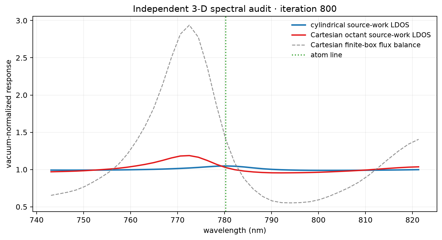
The solid curves compare the same vacuum-normalized dipole source-work observable in both solvers. The dashed Cartesian box-flux curve is retained as an energy-balance diagnostic, but it is not labeled LDOS because residual stored energy can make finite-pulse flux differ from source work.
Numerical contract and current limitation#
parameter |
value |
|---|---|
wavelength |
780.24 nm |
core / fill material |
SiN, n=2.05 / SiO₂, n=1.444 |
initial SiN thickness / allowed range |
250 nm / 100–400 nm |
initial each-side SiO₂ / allowed range |
125 nm / 50–200 nm |
air-hole diameter |
differentiable, ≥1.000 µm |
optimization radius |
4.100 µm |
spectral schedule |
12 → 24 → 36 DCT-II modes |
grid spacing |
25 nm |
radial control pitch / filter radius |
100 / 150 nm |
field cells |
26,832 |
time steps |
7,119 |
rotational mode |
m=0 TM (Er, Ez, Hφ) |
The cylindrical interior update, axis limit, and differentiable conservative CPML are unit/analytic tested; the short-pulse late return is suppressed by more than 500× relative to the PEC boundary. Live LDOS and Q values remain research metrics until PML-thickness stability and the scheduled Cartesian 3-D octant comparison agree. The 3-D audit records a 41-point local spectrum and independent pole fit and remains intentionally separate from the hot-loop objective.
Rejected discovery precursors
V1 used 40 nm fabrication cells and remains rejected for resolution sensitivity. V2 moved to the 25 nm field grid but linear interpolation created a literal 25 nm threshold sliver. A later audit correction found that the huge V1–V4 discrepancies previously shown here were finite-box pulsed flux, not dipole source-work LDOS. Re-audited target-frequency differences are 11.8%, 7.1%, 5.1%, and 1.5% for V1 through V4. V3 is therefore a valid 100 nm precursor retired when CPML arrived; V4’s 200 nm basis is too coarse for the SiN quarter-wave scale. Frozen V6 used the 1 µm hole and whole 4 µm-radius domain. V7 tested a 500 nm hole with Shaker-style successive enlargement. V8 returned to a ≥1 µm hole and added the finite symmetric stack; it was archived at iteration 543 with best projected LDOS 1.1797. Active V9 starts cold in the 12-mode DCT basis, progressively unlocks the complete 36-mode line, and uses the longer field-plus-energy gate before differentiable shifted Q/V. Source-work LDOS, box-flux balance, spectra, and pole fits stay visible.
Last atomic update: 2026-08-24T14:06:56.682039+00:00