Live two-stage Fryett antenna-to-cavity campaign#
Paused coordinate ratchet
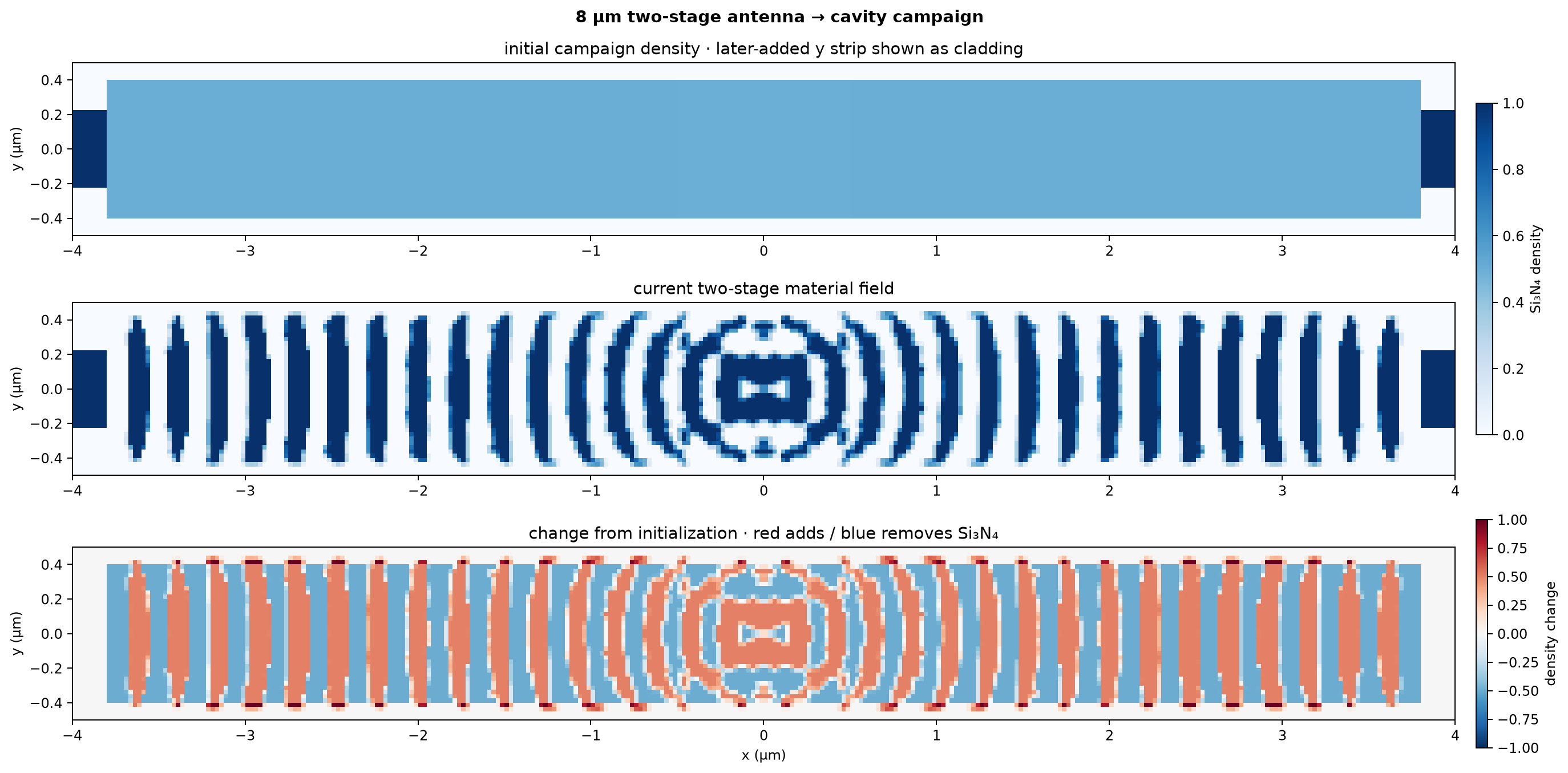
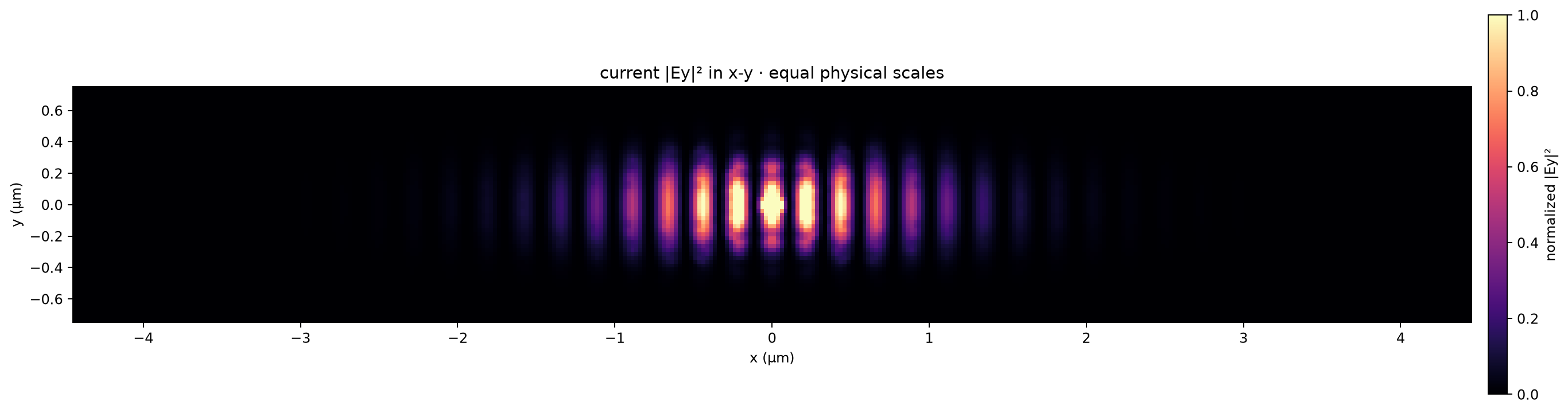
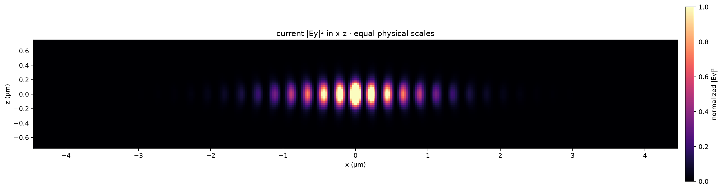
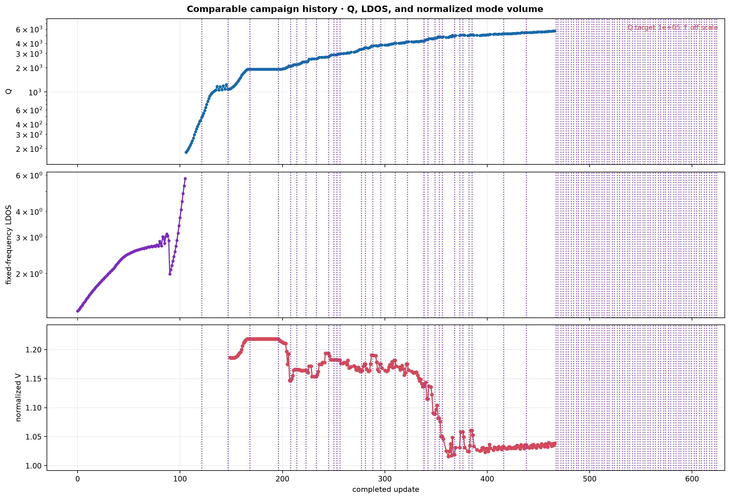
Stage 1 exposes only a 1.0 µm box around the emitter and maximizes LDOS with 400 local pixel controls. Both regions start at neutral material density \(\rho=0.5\), the permittivity midpoint between cladding and SiN, instead of as a waveguide. A short fixed SiN feedthrough remains only at the terminal boundary. Stage 2 promotes the antenna into one 3,200-cell freeform material field covering the complete design box. No interior cell is frozen and there is no prescribed beam, hole profile, period, mirror region, or material sign. A positive-semidefinite multiscale cosine metric makes broad coordinated moves while preserving every pixel degree of freedom; its bandwidth expands to the full grid before binarization. Q ascent retains a strong positive \(\nabla\log Q\) component while adding a bounded lateral move from the learned dark subspace. At update 147 an explicit operator-directed probe replaced the conservative \(Q\ge10^5\) handoff gate: the freeform pattern was made exactly binary, its resonance was replayed, a spline boundary was fitted, and that representation was replayed again. Both tests passed. The corrected smooth-spline objective maximizes \(\log Q\) subject to first-order improvement of both \(Q\) and \(Q/V\). Exact replays require nondecreasing Q and resonant LDOS and enforce normalized \(V\leq 1.25\). A short smoothing metric on the spline controls suppresses corrugated boundary motion without freezing any boundary segment. The failed prescribed-hole branch is preserved as a negative ablation and is not resumed. At update 168 two consecutive topology-safe proposals had zero motion because the 81×9 displacement field had reached its reference range. The accepted boundary was rebased exactly into 41×5 controls, replayed without metric loss, and resumed with fresh coordinate-dependent state. The coarse spline admitted only one 0.125 nm move before the topology guard again returned zero motion. At update 196 an opt-in three-stage coordinate ratchet was prepared around the accepted geometry: cut-cell boundary pixels maximize resonant LDOS, a freshly rebased spline maximizes Q, and coherent outer DCT boundary directions refine PhC-scale interference with a dark localization component. Only cut cells may be fractional; the material bulk stays binary. Every coordinate switch adopts the exact latent level set, and there is no cumulative boundary-displacement cap. At update 338 the accepted pixel chart was widened from ±0.40 to ±0.50 µm in y. The added bulk began as exact cladding, with only the inherited subpixel boundary cut cell; no beam, holes, gray bulk, or period was inserted. A mandatory pole replay retained \(Q=4266.935\), normalized \(V=1.136908\), and peak LDOS \(=285.202\), essentially the pre-expansion values, while the 194×42×42 Maxwell grid stayed unchanged. The state table below is authoritative about whether it is currently running. This page refreshes once per minute.
State |
Value |
|---|---|
Completed updates |
625 |
Phase |
|
Coordinates |
|
Status |
|
Fixed-frequency LDOS |
5.763 |
Q |
5701 |
Normalized V |
1.038 |
Peak resonant LDOS |
417.2 |
V estimator |
|
Low-radiation rank |
0 |
Projection/boundary state |
coordinate ratchet cycle=37, stage=phc_q; coordinates=161×21; trial step=2.53 nm; binary bulk with cut-cell boundary fills; automatic exact rebasing; no cumulative displacement cap |
Gray fraction (0.1–0.9) |
15.12% |
Q/dark direction |
|
Latest differentiated update |
237 s |
Last artifact write |
2026-08-28 14:03:42 UTC |
Normalized V and peak resonant LDOS now use the corrected spectral-branch and same-window RMS estimator. Earlier V points used the invalid estimator and remain quarantined; Q history is retained because independent field- and energy-decay fits agreed.
The full design is 8.0 µm long. Three mirror planes reduce it to a 194 × 42 × 42 Maxwell grid (342,216 cells), an eightfold symmetry saving. During Stage 1 every outer cavity coordinate is absent, so the large domain cannot outcompete antenna formation. The inactive outer region is held at \(\rho=0.5\). At handoff the saved antenna is copied into the same pixel field as the neutral exterior; every interior pixel then moves under one Maxwell objective. The spatially varying optimizer metric changes step correlations, not the material decoder, so it cannot create an interface between different geometry families. If a photonic crystal is useful, its holes and period must emerge from the objective. The operator-directed exact-binary and spline replays are marked in the history. The radiation basis was reset at that coordinate change and is being relearned because its vectors are coordinate-specific.
Geometry and material change#
Current field — x-y row#
Current field — x-z row#
Q, LDOS, and normalized-V history#
I would build this as one continuation-based co-design optimizer: one physical cavity, one global Maxwell solve, but different coordinate systems in different spatial regions and at different maturity stages.
The key is that the antenna and photonic crystal are never optimized as separate devices. They are two coupled parameter blocks of the same dielectric field and the same tracked electromagnetic mode.
2. Use objectives that exist before a cavity mode exists#
A difficulty with genuinely starting from scratch is that \(Q\), mode volume, and even “the cavity mode” may initially be undefined.
I would begin with an emitter-driven broadband FDTD trajectory and extract two complementary quantities:
and
Roughly:
Band-integrated emitter response measures oscillator strength and is primarily sensitive to inverse mode volume.
Persistent late-time response rewards a localized, long-lived resonance.
Radiation-channel power penalizes energy escaping vertically or through the ports.
For a sufficiently isolated Lorentzian resonance, peak LDOS scales like \(Q/V\), while its integrated spectral weight is much more closely connected to \(1/V\). This helps separate “make a strong antenna” from “make its resonance dark.”
The early objective could be
Once a stable pole appears, the optimizer switches from proxies to physical quantities:
The core-energy constraint \(\eta_{\mathrm{core}}\) prevents the optimizer from selecting a remote band-edge mode with tremendous Q but negligible emitter coupling.
3. Optimize the antenna and mirror in the same step#
Write the parameters as
A joint constrained step solves approximately
Both gradients contain both parameter blocks. Consequently, the optimizer can propose a coordinated step like:
Tighten the dielectric antenna and reduce \(V\).
Simultaneously chirp several photonic-crystal periods to recover the resulting radiation loss.
Slightly adjust the transition region to keep the same pole.
That coordinated compensation is exactly what separate near-field and far-field optimizations would miss.
I would not permanently require \(Q_{\mathrm{new}}\ge Q_{\mathrm{current}}\). The physical constraint should normally be \(Q\ge Q_{\mathrm{target}}\). If the cavity has accumulated Q reserve, it should be allowed to exchange some of that reserve for lower mode volume. A filter/SQP method can compare nondominated \((V,Q)\) candidates while remaining above the active Q floor.
4. Treat darkness at the amplitude level#
This is an important improvement over simply differentiating \(Q\).
Let \(a_c\) be the complex outgoing amplitude in radiation channel \(c\):
Fourier components inside the vertical light cone.
Forward and backward waveguide-port modes.
Any substrate or polarization channels.
Then
Near a dark state,
which becomes small as \(a\rightarrow0\), even though the Jacobian
still contains crucial information about which coordinated perturbations remain dark. Locally, the radiation curvature is approximately
This is the rigorous version of the low-radiation subspace we have been approximating with Q-gradient secants.
I would extend it by:
Recording outgoing complex channel amplitudes, not only total radiation loss.
Occasionally differentiating a few randomized combinations of those channels.
Building a low-rank approximation to \(J_{\mathrm{rad}}^\dagger J_{\mathrm{rad}}\).
Projecting the mode-volume proposal into its low-singular-value subspace.
Still validating every proposal with the complete global FDTD solve.
This directly learns collective cancellation directions. Light-cone suppression is a known route to high-Q photonic-crystal cavities. Optimization of Q through Fourier/light-cone control
5. Continue from density to boundary optimization#
I would use four phases, all in one checkpointed campaign:
Phase |
Geometry coordinates |
Main purpose |
|---|---|---|
Discovery |
Local wavelets/pixels + windowed Bloch modes |
Nucleate an antenna, mirror, and localized resonance |
Mode capture |
Same basis with finer core resolution and slower PC envelopes |
Track one emitter-coupled pole and raise its Q |
Binarization |
Increasing projection strength and minimum-feature filtering |
Produce an unambiguous dielectric boundary |
Boundary refinement |
Boundary-normal motion in localized and Bloch-envelope bases |
Minimize exact \(V\) subject to exact Q and radiation constraints |
At the density-to-boundary handoff:
Extract the zero contour.
Reproduce the density with a level set.
Replay the same geometry electromagnetically.
Clear only coordinate-dependent curvature.
Preserve the pole, objective history, multipliers, radiation-channel model, and Q target.
Unlike our present implementation, I would store the learned radiation-sensitive vectors in physical density or normal-boundary-displacement space. Then the dark-mode knowledge can survive a pixel-to-boundary or spline-to-level-set conversion.
6. Make spatial resolution adaptive#
The core/mirror transition does not need to be permanently hand-selected. Start with a hierarchy of localized Bloch-wavelet functions and measure each candidate basis function by something like
A large \(\eta_j\) means the mode can improve emitter confinement without strongly opening radiation channels.
The optimizer can then:
Add fine localized functions where \(\eta_j\) is large—probably near the emitter.
Retain broad Bloch-envelope functions farther out.
Remove variables whose physical influence is negligible.
Move the transition region as the cavity develops.
This turns “antenna near, photonic crystal far” from a hard-coded rule into an emergent allocation of degrees of freedom.
The complete picture#
The resulting process is:
blank dielectric design region
        ↓
broadband emitter excites candidate structures
        ↓
local freeform antenna + distributed Bragg pattern emerge together
        ↓
one emitter-coupled pole becomes trackable
        ↓
radiation-channel Jacobian learns coordinated dark motions
        ↓
material projection forms a binary boundary
        ↓
boundary-normal co-optimization reduces V while the outer PC restores Q
The adjoint remains global throughout. Every core change “knows” about the photonic crystal, and every photonic-crystal change “knows” about the field at the emitter. The heterogeneous basis changes what motions are easy to propose; it never decomposes the physics into separate cavities.
This also matches the empirical observation that substantial reductions in mode volume usually require genuine core/topology changes, whereas increasing device extent often raises Q without proportionally reducing V. Topology-optimized high-\(Q/V\) cavities