
Device 23 anthracene-cavity LDOS optimizer#
Live free-form campaign
This page is rebuilt from the optimizer artifact and published every minute.
The trainable object is a 9.3 × 1.0 µm two-dimensional Si₃N₄/air pixel mask
extruded through the complete 300 nm nitride film. Anthracene, PVA, and the
SiO₂ substrate are immutable and unetched. Updated: 2026-08-24T14:46:54.887927+00:00.
Reconstruction target and forward qualification#
The source is the published Device 23 full-boundary campaign.
Its final physical checkpoint has λ=768.555 nm,
Q=1183.52. The unavailable numeric 4 nm level set was
reconstructed from the lossless matched-axis geometry PNG. The PNG hash,
coordinate calibration, 40 fitted hole contours, and ~5.1 nm raster uncertainty
are stored in device23_geometry.json.
FDTDX finds one clean corresponding pole at 757.888 nm, Q=1662.36, with fit error 2.10e-05. The 20 and 25 nm area-averaged grids agree in wavelength to 0.02 nm. The remaining 1.39% frequency offset is retained visibly as a fixed reconstruction/discretization calibration; it is not retuned during optimization. The raw FDTDX Q is 1.405× the Tidy3D value, so Q is tracked as useful solver telemetry rather than claimed as cross-engine parity.
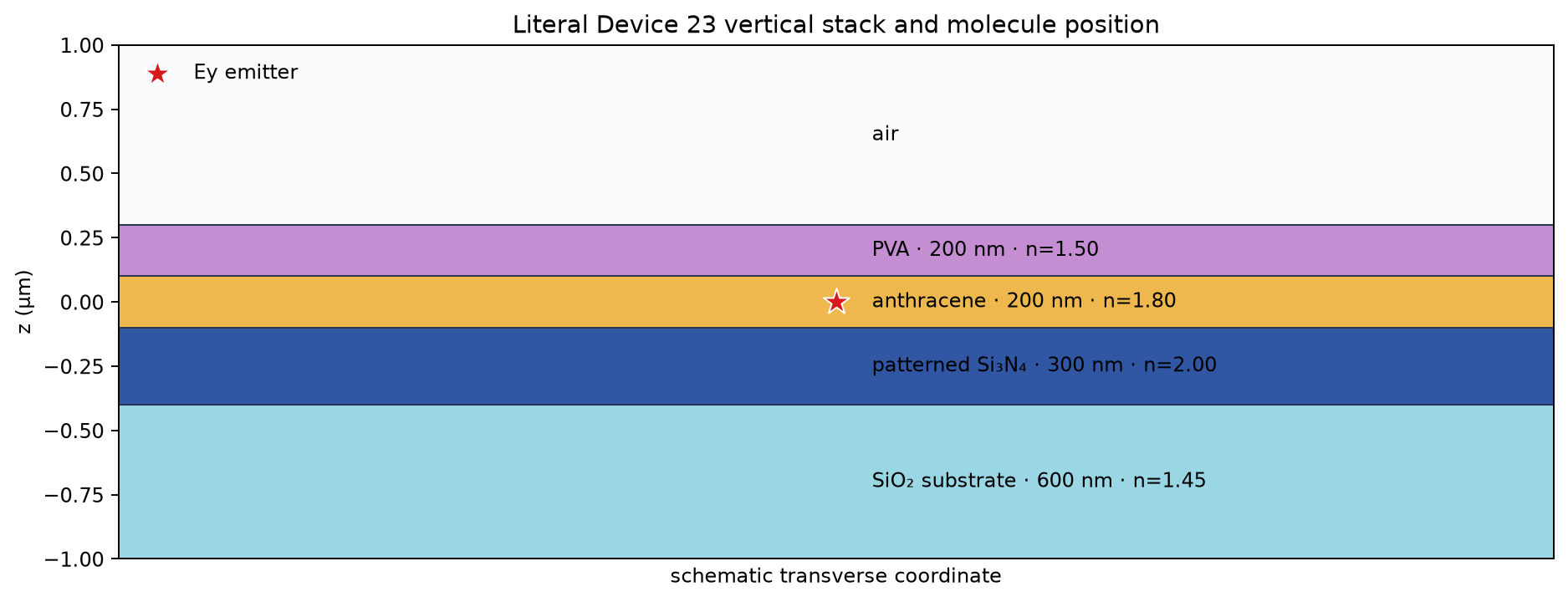
The red star is the Ey-oriented emitter at the centre of the 200 nm anthracene film. Holes and later topology changes etch only Si₃N₄; the plane of the cavity is air wherever nitride is absent.
Initial and evolving single-etch mask#
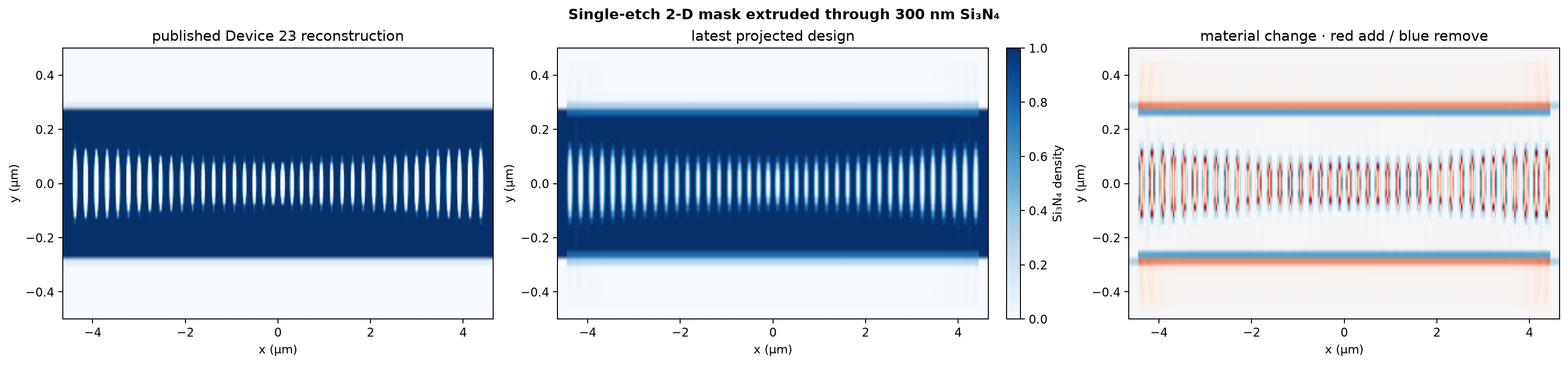
Only the positive x/y quadrant is simulated, using the exact (1, -1, 0)
parity of a centred Ey dipole. The displayed mask is unfolded for inspection.
A 50 nm conic filter, η=0.45/0.50/0.55 morphology cycle, pinned terminal
waveguide, and 50 nm outer-air rail prevent the optimizer from exploiting the
edge of the 1 µm-wide design region.
Fields at the molecule, cavity, and complete vertical domain#
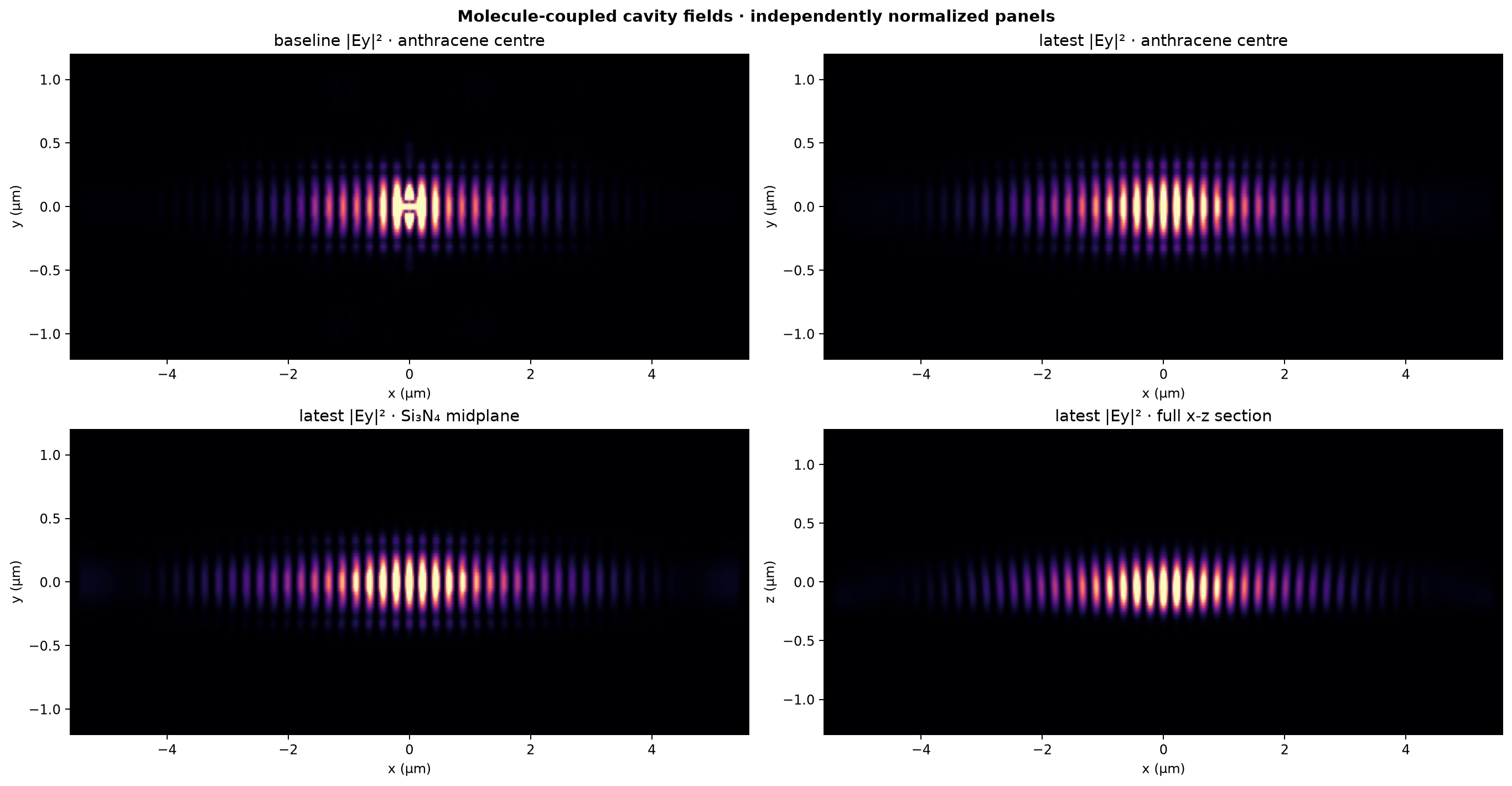
Every field panel is a literal FDTDX phasor and is normalized independently so that the molecular-plane evanescent field remains visible beside the stronger Si₃N₄ field. The x-z panel includes the complete z extent through both PML interfaces.
Objective and history#
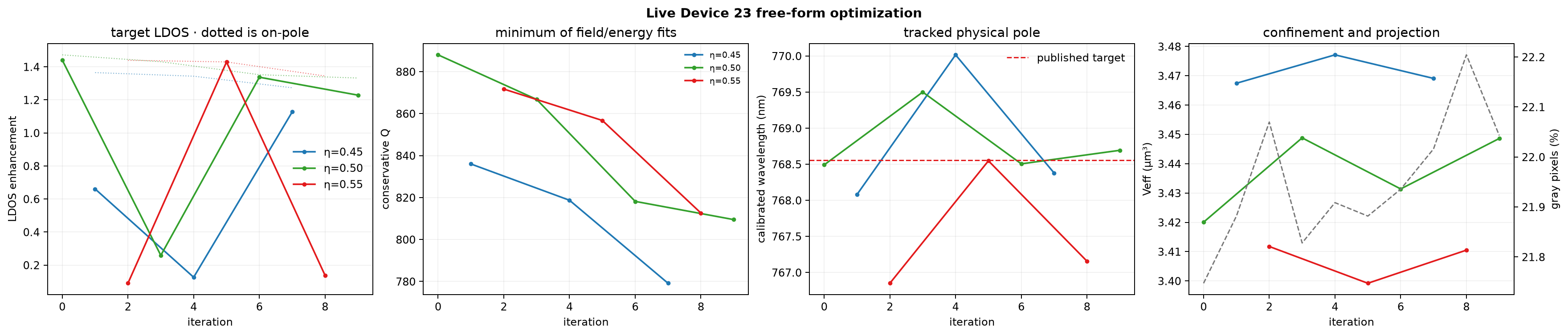
The differentiated objective is
Adjacent iterations intentionally evaluate different robust projections. The history therefore draws η=0.45, 0.50, and 0.55 as separate colored tracks; only points with the same η should be compared as a trajectory. Dotted LDOS curves show the corresponding on-pole value before target-line detuning.
A short pulse fits the field and stored-energy decay independently; the lower Q is used. The pole is recentered between coherent fits with stopped gradients, which is the Shaker-style shift that avoids differentiating the pole-motion Hessian. Steps fail closed if either residual exceeds 18%, the two Q estimates differ by more than 2×, or the calibrated pole leaves the declared tracking window. Full binarization is deliberately slow and reaches β=64 after roughly 600 accepted iterations.