
Fryett encapsulated nanobeam · staged inverse design#
Live campaign
This page is rebuilt from the persistent optimizer checkpoints and published every minute.
Stage 1 is preserved as completed_handoff_to_boundary_stage at iteration 23;
its last checkpoint is 2026-08-24T18:35:05.063319+00:00. The later sections contain the independent
boundary-normal branches and the verified low-radiation mode-volume campaign.
Download the fabrication layouts#
Download every GDS file as one ZIP bundle · combined all-stages GDS library · machine-readable manifest and checksums
Preserved geometry |
State |
Direct GDS |
|---|---|---|
Published arXiv v1 seed |
unoptimized |
|
Published ACS-text seed |
unoptimized alternative |
|
151-parameter ellipse result |
optimized Stage 1 handoff |
|
Level-set zero-motion handoff |
Stage 2A start |
|
Level-set terminal cavity |
optimized Stage 2A |
|
Cubic-spline zero-motion handoff |
Stage 2B start |
|
Cubic-spline terminal cavity |
optimized Stage 2B |
|
Low-radiation spline handoff |
immutable Stage 3 start |
|
Low-radiation current cavity |
live accepted Stage 3 state |
All layouts use micrometre coordinates and a 1 nm database unit. Layer 1/0 is the authoritative positive-SiN device; layer 2/0 contains the 100 hole apertures separately for inspection or a holes-only process. The masks are fully unfolded and include 2 µm of fixed 450 nm-wide feedthrough at each end. GDS is only the in-plane single-etch mask: the 330 nm SiN thickness and the oxide/organic cladding stack shown above are process metadata, not GDS layers. The bundle contains a README with this layer map and tape-out caveats. It was generated from 9 preserved geometries.
What was reproduced#
The seed is the encapsulated Si₃N₄ nanobeam from Fryett et al., arXiv:1709.02032: a 330 nm × 450 nm beam in index-1.47 cladding, 233 nm Bragg pitch, 100 × 300 nm elliptical mirror holes, a roughly 2.04 µm taper, and 40 saturated mirror periods per side. The full simulation retains all 50 holes per side and the beam continues through the x PML.
The preprint and final journal prose disagree on the innermost ellipse. Both literal variants were screened. The selected arxiv_v1 seed has a dominant FDTDX pole at 780.550 nm. On the 2 ps qualification tape its conservative differentiable fit gives Q=1.5598e+05, V=0.8198 µm³, and Q/V=1.9027e+05 µm⁻³. The paper’s nominal 740 nm target is quoted rather than forced: the 25 nm Yee-grid reconstruction is visibly red-shifted.
Why this branch restarted#
The preceding continuous-pixel branch improved Q/V from 1.9027e+05 to 2.7691e+05 µm⁻³, then rejected 3 consecutive trial steps. It was stopped as plateaued. This campaign does not inherit that density, momentum, or pole history.
The replacement begins at exactly the paper ellipse parameters. Its optimizer moments, learning-rate history, accepted-step history, and shifted tracking state all begin at iteration zero.
Layer stack used by the simulation#
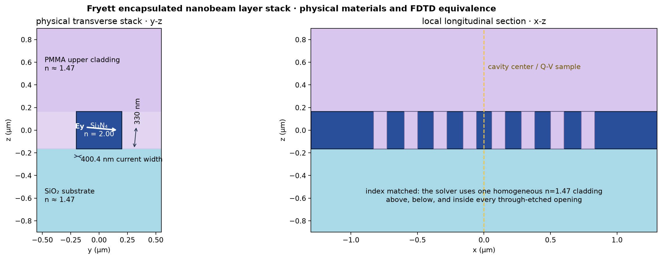
The physical device places the 330 nm Si₃N₄ beam on thermal SiO₂ and encapsulates it from above with PMMA. Both surrounding materials have approximately the same refractive index, 1.47, so they form an optically continuous cladding. FDTDX therefore represents them—and the material filling every through-etched opening—as one homogeneous index-1.47 background. This avoids inserting a fictitious interface at the beam midplane. The trainable x-y mask is extruded only through the 330 nm nitride thickness; neither cladding is a design variable.
Geometry: published seed, current ellipses, and exact change#
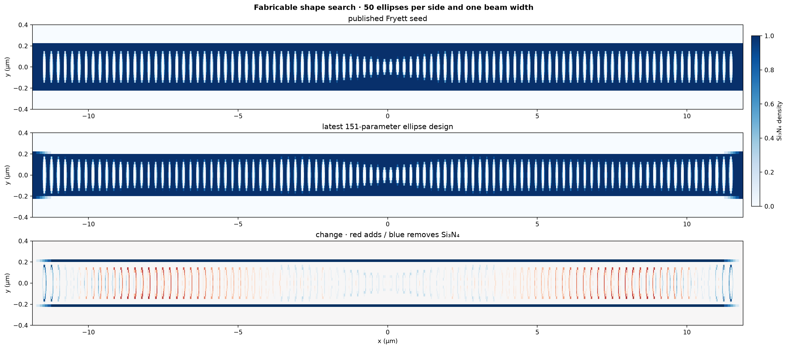
GDS downloads: arXiv seed · ACS seed alternative · optimized ellipse handoff
This branch is deliberately not a free-form pixel search. Each of the 50 positive-side holes has an independent center position, longitudinal diameter, and transverse diameter. Mirror symmetry generates the negative side, and one more variable changes the beam width: 151 physical controls in total. The current longitudinal diameters span 80.8–120.5 nm and the transverse diameters span 145.5–359.8 nm.
Position bounds of ±30 nm and longitudinal diameters of 60–140 nm guarantee that ellipses cannot cross; even the worst allowed central pair retains a 15 nm Si₃N₄ bridge. Transverse diameters are bounded to 80–360 nm. The beam is 400–700 nm wide through the cavity and returns smoothly to the fixed 450 nm feedthrough over the final 750 nm, so it still crosses the x PML without a dielectric termination. The displayed mask is the physically unfolded design.
Center field, including the complete vertical section#
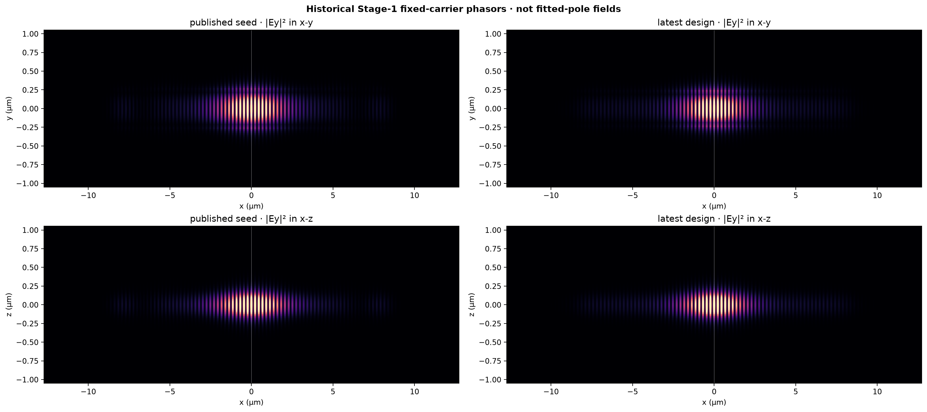
The centered dipole and objective use Ey, the cavity polarization reported
for this design. The x/y mode parity is (magnetic, electric) and identical
upper/lower cladding supplies z magnetic parity, giving FDTDX symmetry
(1, -1, 1). These archived Stage-1 panels were demodulated at the original
780.550 nm pulse carrier and are retained only as historical driven-response
plots; they must not be interpreted as the later fitted pole. The corrected
pole-aligned Stage-2 fields are displayed above with both detector and fitted
wavelengths printed on the figure.
Q/V objective and shifted pole tracking#

Exploratory stage now frozen
This objective followed the moving cavity pole from 780.550 nm toward 769 nm. Its Q/V history is useful shape-search evidence, but it is not accepted as fixed-emitter LDOS improvement. The matched shifted-LDOS branches below correct that objective error and compare two boundary parameterizations.
Each accepted step maximizes log(Q/V) at the cavity center. Q is the lower of
an Ey complex-pole decay fit and an independent total-energy decay fit. V uses
the late modal energy divided by the local center-field intensity and local
Si₃N₄ permittivity. The fit follows the measured pole between steps with a
stopped-gradient frequency shift, avoiding the ill-conditioned pole-motion
term while retaining differentiation through the short FDTD ringdown.
The forward geometry is binary Si₃N₄/cladding and is rasterized with a 6×6 subcell area average. A narrow smooth surrogate exists only in the backward pass to provide derivatives of the ellipse boundaries and beam edge; it never turns a hole into a gray material parameter. Bounded Adam steps use monotonic backtracking, and the learning rate halves after a rejected attempt rather than repeating the same failed step indefinitely. Trial steps are accepted only when Q/V does not decrease and both decay fits pass residual, consistency, Q-ratio, and tracking-window gates.
Matched-start method comparison#

Both curves include their independently replayed zero-displacement handoff as step zero. Comparing by adjoint step measures optimizer efficiency; the final panel separately shows accumulated GPU wall time, including line-search forward trials. Neither branch inherits geometry or L-BFGS curvature from the other.
Stage 2A — level-set boundary optimization with L-BFGS#
Active continuation
This is a clean optimizer stage below the preserved parametric record. It
inherits the complete iteration-23
geometry but no ellipse controls, Adam moments, or superseded boundary steps.
The stage is currently
stopped_plateau_user_requested at boundary iteration
79. Last checkpoint: 2026-08-25T11:12:52.341919+00:00.
Superseded frequency-correction attempt
The first boundary attempt fixed the objective at 780.550 nm instead of the boundary handoff’s own pole. It spent 6 steps broadening Q from 893,193 to 965.69 while trying to cover that 11 nm detuning. It is archived intact, but its history is excluded from the fresh curve below because frequency correction is not the present goal.
Superseded hard-raster attempt
The next fixed-line attempt was stopped after 7 nominally accepted steps because its hard 6×6 forward occupancy never changed: the density and fields remained bitwise identical. Its checkpoint is preserved, but none of its displacement, momentum, or history enters this restart.
Boundary-stage geometry#
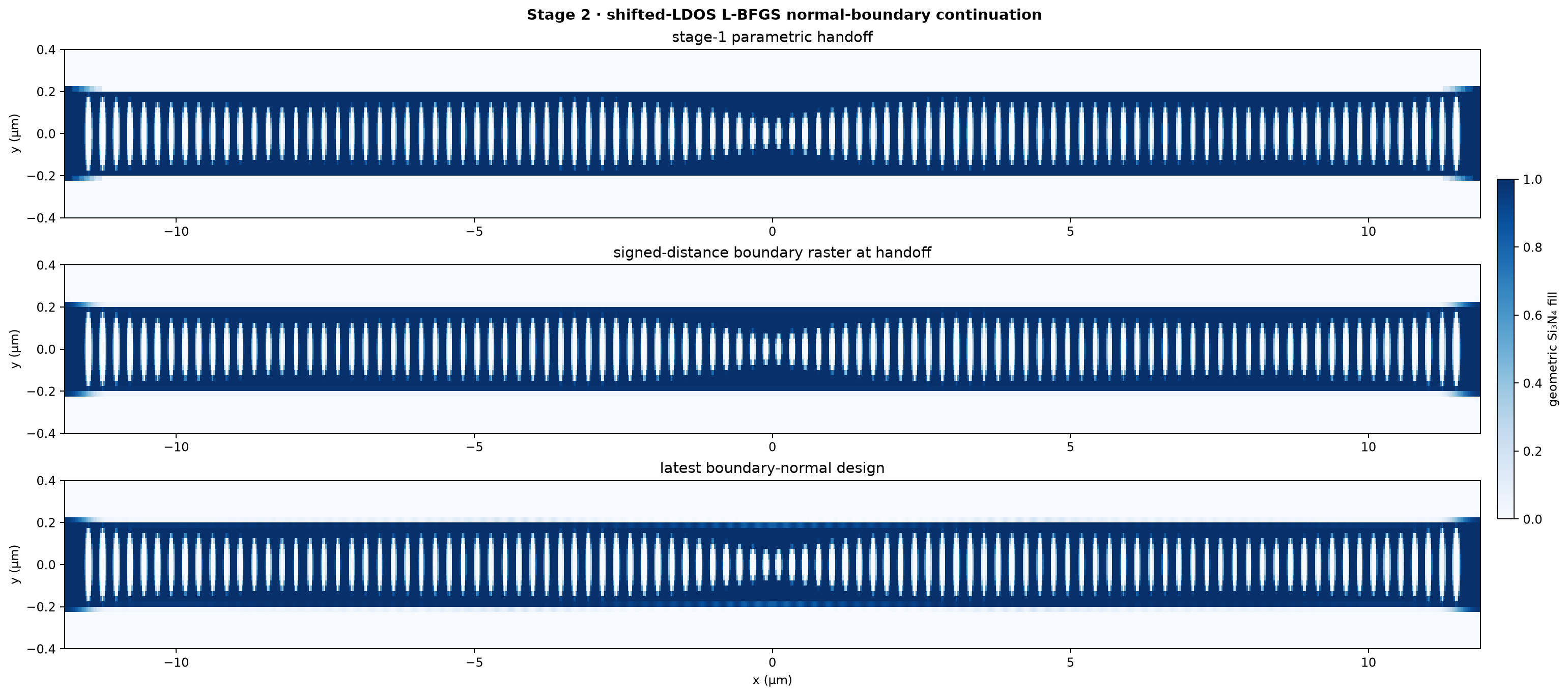
GDS downloads: stage start · final optimized boundary
The middle panel is the one-time signed-distance conversion of the parametric handoff. Fractional edge cells are continuously differentiable geometric 6×6 subcell coverage, not grey design variables. Uniform cells remain exactly binary. Its mean absolute fill difference from the exact parametric raster is 0.633%. An independent zero-displacement replay retains Q=8.5692e+05 at 769.622 nm, so this is the same high-Q pole family rather than the rejected thresholded handoff. From that point onward, each parameter is a signed normal displacement of an existing interface. Positive motion grows Si₃N₄ and negative motion retreats it. The outer 750 nm feedthrough is fixed so the beam still enters the x PML without a termination.
The initial topology has one connected Si₃N₄ body and 50 enclosed holes in the stored x/y quadrant. Symmetry-plane half-holes are counted after unfolding. Every proposed step must preserve one-to-one component and hole lineage, so a hole cannot vanish while another appears elsewhere.
Eigenfrequency-shifted objective#

The handoff pole at 769.622 nm identifies the mode family. At every
iteration, differentiable ringdown fitting returns the current pole
ω*(geometry), and the optimized quantity is
log LDOS_peak(Re[ω*(geometry)], geometry).
This is the time-domain analogue of the Shaker eigenfrequency-shifted formulation: the evaluation follows the peak, eliminating the narrow fixed-frequency ridge. A broad ±2.0% frequency constraint prevents mode switching without forcing the pole to stay within a physical linewidth. The initial-frequency Lorentzian is displayed only as a diagnostic.
The boundary controls pass through a 50 nm spatial filter, then through the continuous subpixel fill calculation used by the actual FDTD permittivity. L-BFGS constructs its direction from exact autodiff gradients and up to 8 accepted secant pairs. An Armijo line search chooses the accepted distance; the geometric move limit is only a topology/fabrication trust region. Equal-score or unchanged-material proposals are not accepted.
The dashed orange marker records the controller change after 27 completed boundary updates. From that point, the first line-search scale may exceed one, only two forward trials are allowed, and the trust radius follows actual/predicted objective agreement. It is no longer collapsed merely because a smaller Armijo trial succeeded. The level-set radius begins this continuation at 2.5 nm and may grow to 7.5 nm.
Per the present campaign protocol, no periodic exact-binary validation solve is performed during this stage.
Boundary-stage fields#
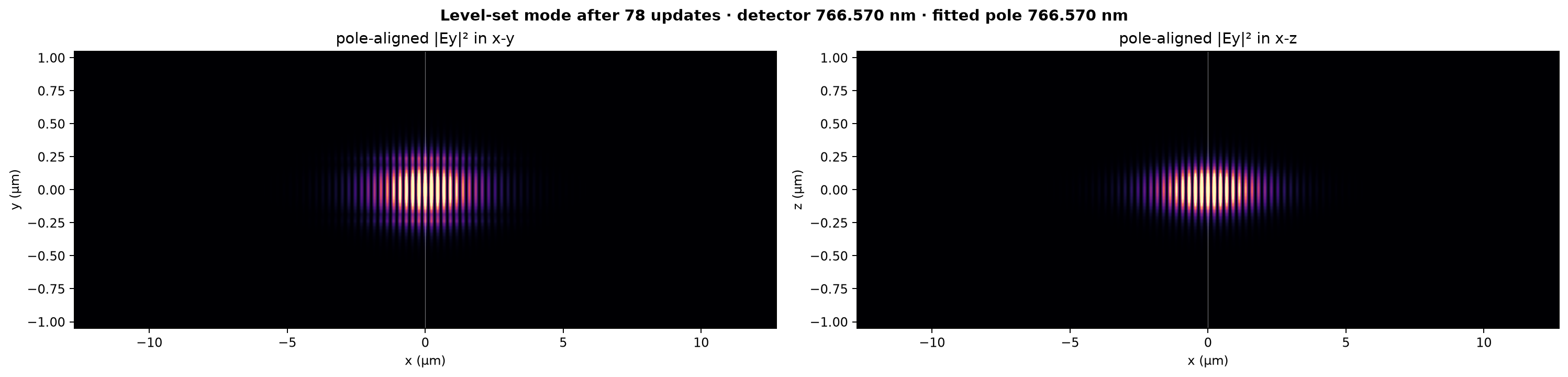
These are pole-aligned field audits, not the original fixed-carrier phasors. The detector wavelength and independently fitted wavelength are printed above the panels. The audit stores the geometry it actually measured and can trail the newest accepted boundary by at most one shared-GPU update. Panels are normalized independently for spatial inspection; scalar LDOS and Q values come from the unnormalized ringdown tape.
Zoomed boundary field with the etched geometry#
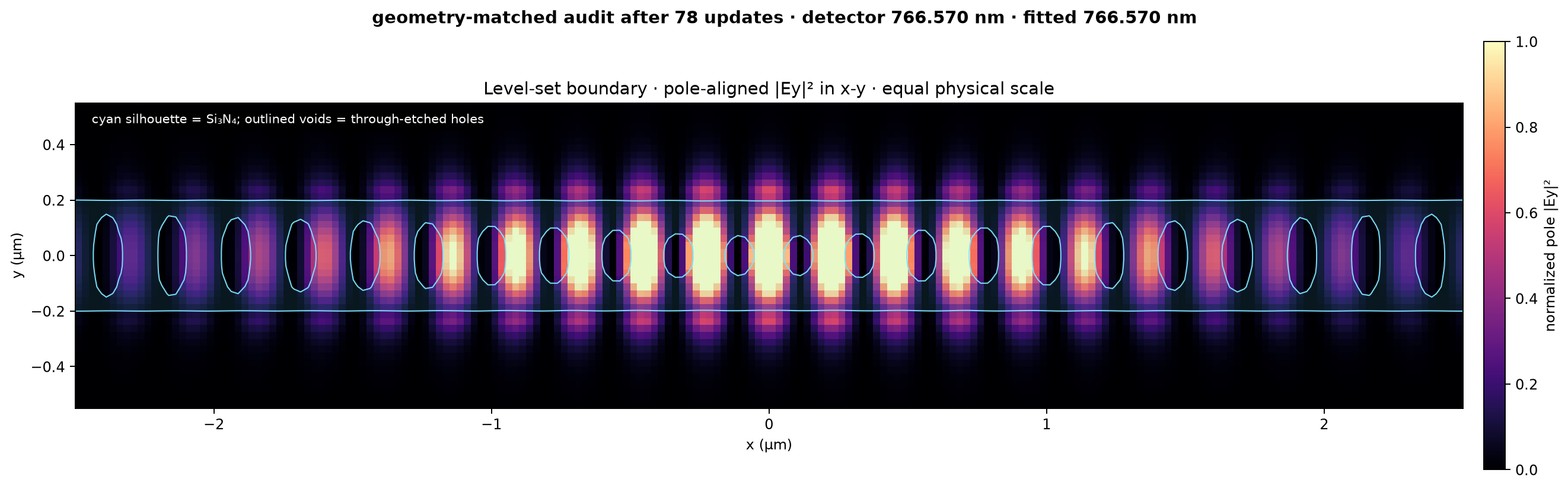
Open the full-resolution xy PNG.
The x and y axes use the same physical scale, the view is restricted to
-2.5 to +2.5 µm, and the cyan silhouette is the exact
pole_field_density checkpoint measured by the field audit. It therefore
shows directly whether each antinode lies in SiN, a through-etched hole, or
the surrounding cladding.
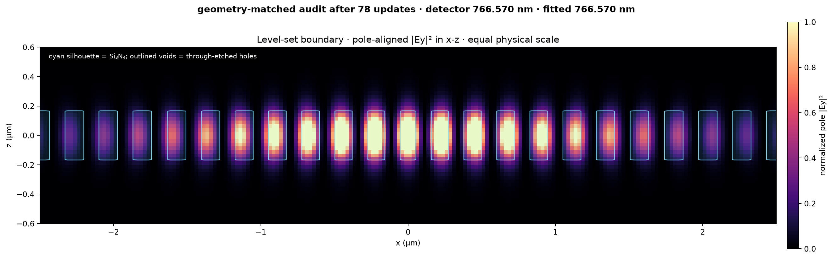
Open the full-resolution xz PNG. This panel also has equal physical scaling. Its cyan silhouette is the 330 nm SiN cross-section evaluated on the y=0 symmetry plane, including the gaps made by every hole crossing that plane.
Stage 2B — explicit cubic-spline boundary optimization#
Independent matched-start campaign
This branch starts from the same terminal stage-1 ellipse geometry and uses
the same FDTD scene, symmetry, shifted peak-LDOS objective, 2% pole guard,
L-BFGS memory, and Armijo acceptance rule as Stage 2A. It is currently
stopped_plateau_user_requested at update 74. Last checkpoint:
2026-08-25T11:18:26.709277+00:00.
Spline geometry#
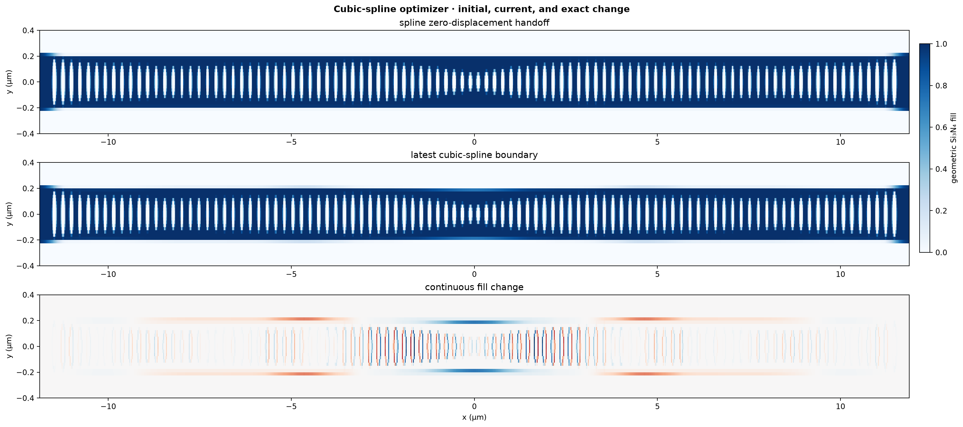
GDS downloads: stage start · final optimized spline
Each positive-side hole has one movable x center and nine cubic radial displacement knots. Reflecting the radial spline at angles 0 and π makes its slope vanish on the y symmetry plane. Forty-eight cubic controls move the positive-quadrant beam edge, with an analytic taper forcing displacement and slope back to zero at the fixed PML feedthrough. The initial spline raster differs from the stage-1 parametric raster by 0.633% mean fill.
Unlike the 8,092-control level set, this 548-control model cannot create fine independent corrugations between spline knots. That is the intended tradeoff: a smaller search space and smooth boundaries in exchange for less free-form geometric freedom.
Spline optimization history#
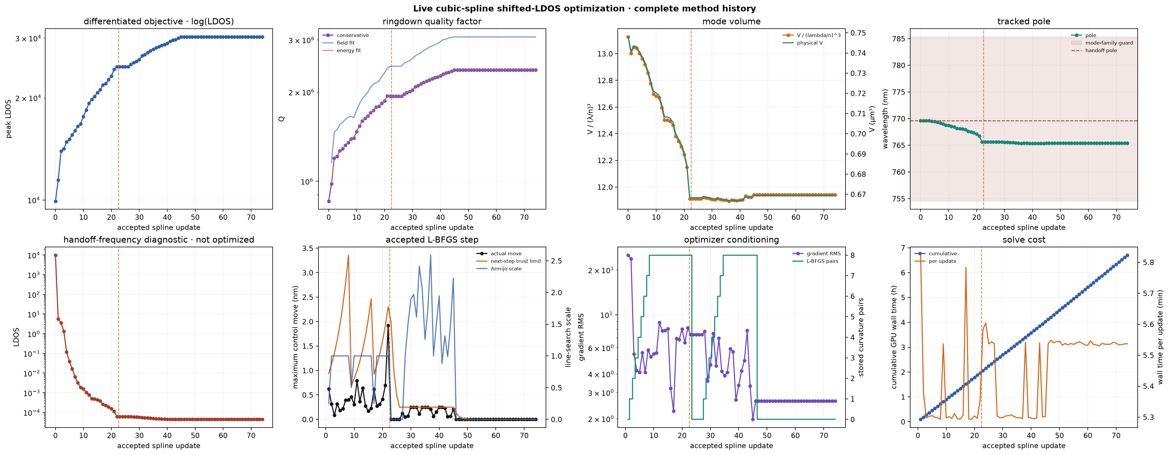
This is the spline worker’s complete independent history, not the shared comparison plot. Step zero is its own zero-displacement FDTD handoff replay. The upper row shows the differentiated shifted peak-LDOS objective, all three ringdown Q estimates, normalized and physical mode volume, and tracked pole. The lower row separates the fixed-handoff-frequency LDOS diagnostic from the objective and exposes the accepted Armijo step, gradient scale, accumulated L-BFGS memory, and GPU solve time. A falling fixed-frequency LDOS is therefore not mistaken for failure when the optimized pole has shifted.
The orange next-step trust limit is an optimizer control, not a measured device property. A full Armijo step expands it by 20%; a backtracked accepted step resets it to 1.5 times the motion that actually worked; and a completely rejected proposal halves it. The resulting sawtooth prevents repeated large geometry proposals while allowing the cap to recover after successful full steps.
The dashed orange marker records the replacement of that legacy rule after 22 completed spline updates. The active controller may expand the L-BFGS scale above one, chooses an aggressive trial before spending a forward solve, and permits at most two FDTD line-search trials. Its trust radius stays unchanged after an adequately predicted accepted step, grows 1.5× only when a good step uses most of the available radius, and shrinks only after poor actual/predicted agreement or complete rejection. The spline radius restarted at 4 nm and may grow to 10.0 nm.
Spline fields#
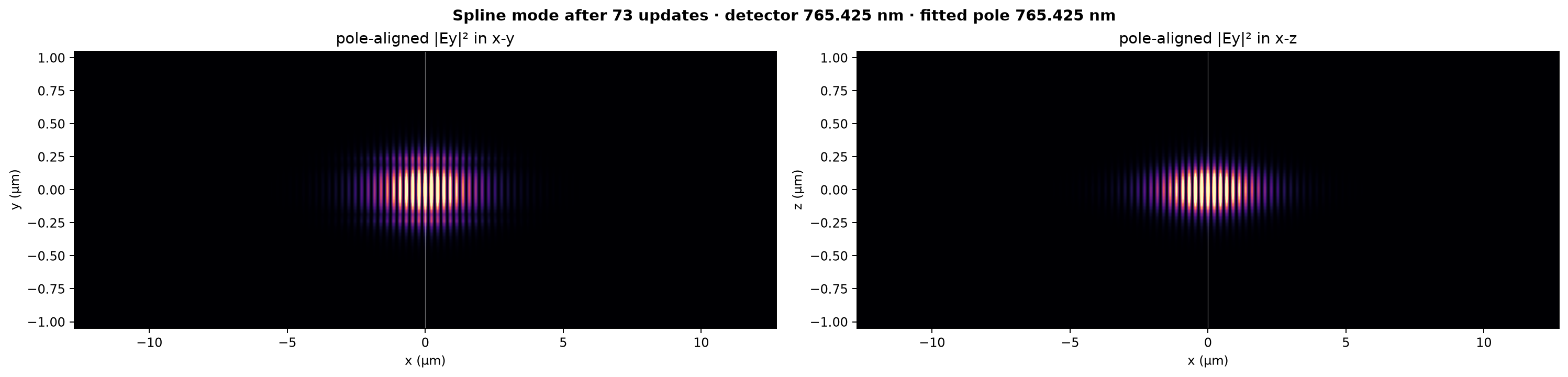
These are pole-aligned field audits, not the original 780.55 nm fixed-carrier phasors. The detector wavelength and independently fitted wavelength are printed above the panels. The audit can trail the latest accepted geometry by at most one shared-GPU update.
Zoomed spline field with the etched geometry#
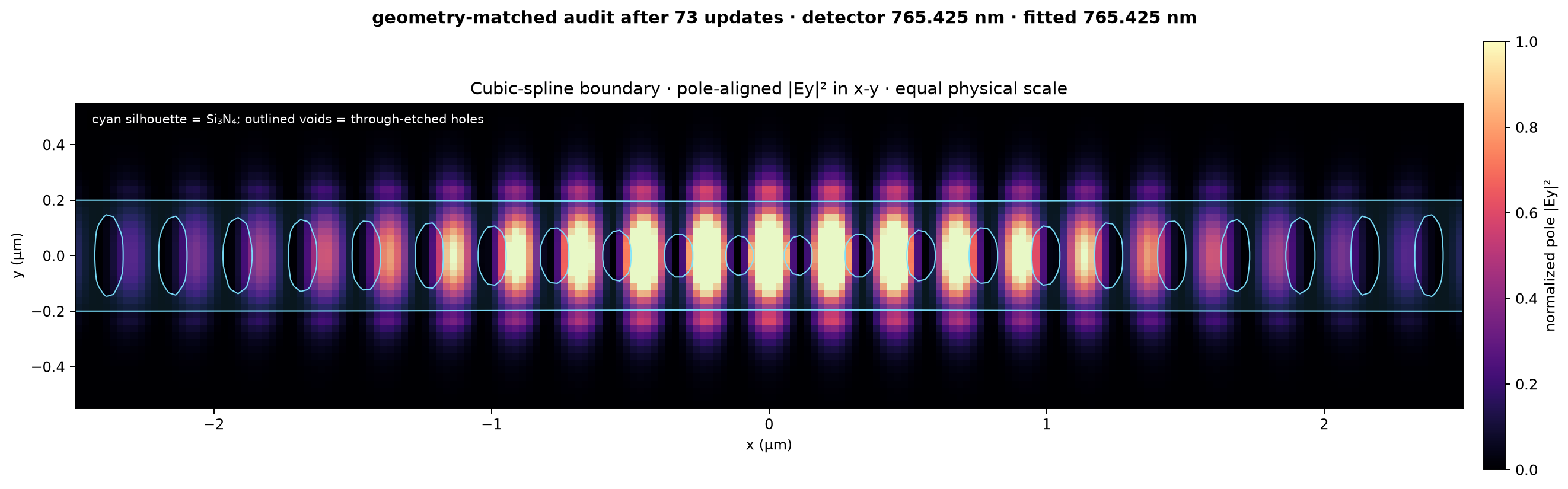
Open the full-resolution xy PNG. The plot uses a true 1:1 spatial scale and overlays the geometry stored with this pole field, not the other optimizer’s mask.
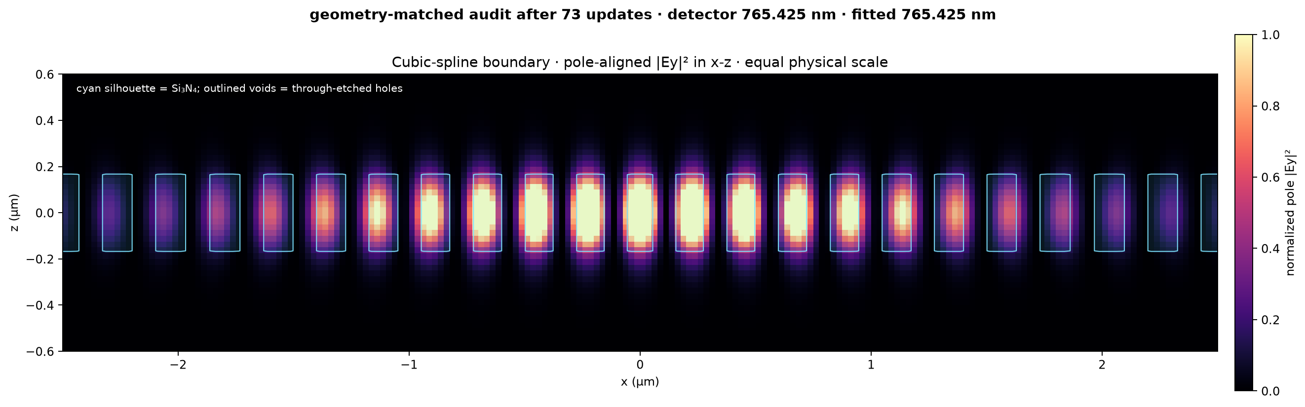
Open the full-resolution xz PNG.
The two optimizers take turns under one process-shared GPU lock. Each turn is one complete adjoint update plus any required forward Armijo trials; neither worker can overlap a Maxwell solve with the other.
Stage 3 — low-radiation subspace mode-volume optimization#
Last independent replay passed
The independent best-design replay passed
the Q, pole-tracking, fit-quality, and topology gates. The audited checkpoint is
2026-08-26T10:49:12.588135+00:00.
Spline handoff geometry#

GDS download: initial Stage 3 cavity
Current checkpoint geometry#

GDS download: current accepted cavity — update 101
These are native boundary exports, not contours traced from the dashboard pixels. The initial file is the immutable spline start; the current file is rebuilt from the latest accepted cubic spline whenever this dashboard refreshes.
Added and removed dielectric#

Red is dielectric added relative to the spline handoff; blue is dielectric removed. White cells are unchanged.
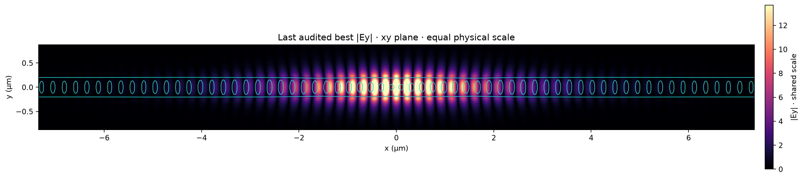
Audited xy field#
Audited xz field#
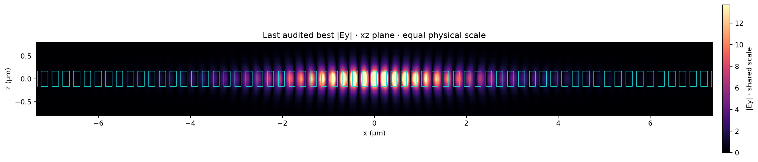
Each geometry and field occupies its own full-width row. Both field panels use equal physical x/transverse scaling, one shared absolute color normalization, an automatic crop around the localized mode, and the matching audited geometry in cyan. While the optimizer is running, the current geometry can lead the independent field audit; the field rows update to the new best when the batch finishes its exact replay.
This branch starts from the terminal cubic-spline cavity and minimizes mode volume while enforcing Q ≥ 100,000. The last independent replay has a 23.143% smaller physical mode volume, Q=104,063, peak LDOS 1,650.7, and normalized V=9.581. The field rows use that independently replayed geometry rather than an in-loop estimate.
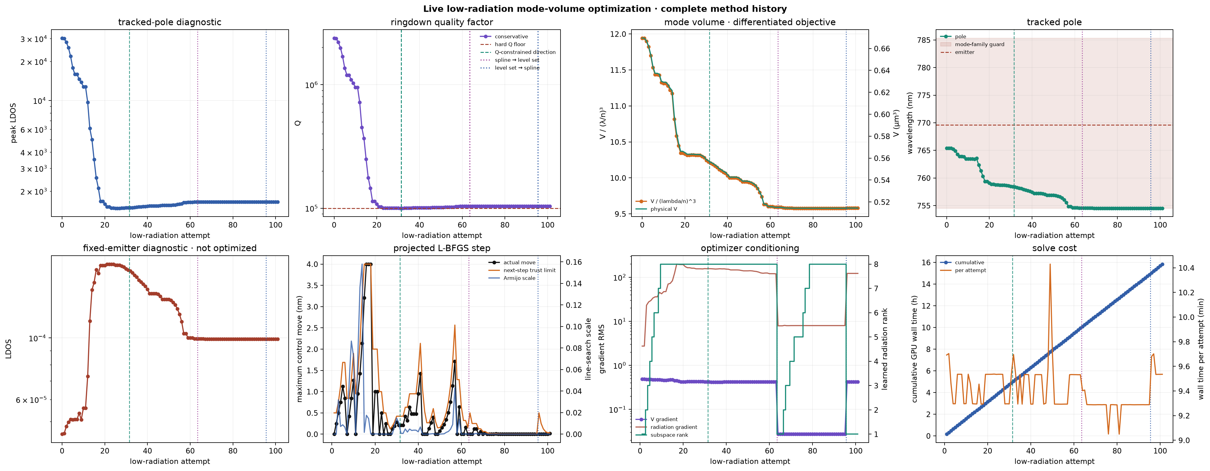
This uses the same 2×4 history layout as the cubic-spline campaign above: tracked-pole peak LDOS, conservative Q, normalized and physical mode volume, pole wavelength, fixed-emitter LDOS, accepted motion and trust limit, optimizer conditioning, and GPU solve cost. Peak LDOS is the cavity Purcell factor at the tracked pole; the lower-left fixed-emitter panel is diagnostic only. Normalized volume is V / (λ/n)³ at each fitted pole.
After 31 completed attempts, Q
reached the hard floor and the proposal rule changed at the dashed green line.
The current full ∇log(Q) now defines an explicit feasible half-space. The
L-BFGS mode-volume proposal is projected into it with a
2.0% first-order Q
margin, and a candidate is accepted only when the forward solve measures
Q_new ≥ Q_current. This is stronger than merely remaining above the
absolute floor.
After 63 completed attempts, the accepted spline boundary was converted exactly into a zero-displacement free level set, marked by the dotted purple line. The material-map change at conversion was at most 5.96e-07. Its independent Maxwell handoff replay passed. Coordinate-dependent L-BFGS curvature, radiation secants, and the learned dark basis were cleared; the full Q gradient restarted the dark constraint in the new 7,565-variable space.
After 95 completed attempts, the accepted free boundary was projected back into the 548 cubic-spline coordinates, marked by the dotted blue line. The closest spline fit changed the fill map by RMS 0.00015 and maximum 0.00353. Its independent Maxwell handoff replay passed. Coordinate-dependent curvature and the learned dark basis were restarted, while the objective, nondecreasing-Q rule, history, and every forward acceptance gate remained unchanged.
The adjoint solve still supplies the ordinary first-order mode-volume and radiation-loss gradients. The optional projector learns directions that are radiation-sensitive from the current gradient and accepted secants, then removes those components from the proposed mode-volume step. This makes a coordinated many-boundary change available to the optimizer without forming a dense electromagnetic Hessian. Every trial still passes the full forward Maxwell audit, the hard-Q constraint, an Armijo decrease test, pole and fit checks, and the original topology gate.