
The FDTDX mental model#
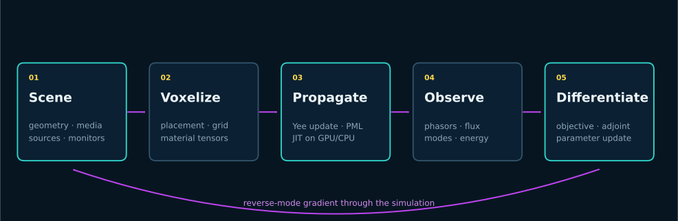
FDTDX separates what the scene means from the arrays a device executes. That distinction is the key to readable simulation code and differentiable design.
Five representations#
Layer |
Purpose |
Typical types |
|---|---|---|
Configuration |
numerical time, grid, dtype, gradient strategy |
|
Objects |
semantic parts of a scene |
|
Constraints |
relationships used to place objects |
coordinate, face, center, size, and relative-placement constraints |
Arrays |
dense state consumed by the time stepper |
fields, inverse permittivity/permeability, conductivity, detector state |
Parameters |
differentiable degrees of freedom |
PyTrees mapped by |
Why placement is explicit#
A photonic component is easier to maintain when “the monitor is 1 µm after the device” is a relationship rather than a copied grid index. Placement constraints resolve physical intent only once the grid is known. This also makes resolution sweeps safer.
Why immutable updates matter#
JAX traces pure array programs. FDTDX objects use functional updates such as .aset(...); state changes are returned instead of mutating shared Python objects. Keep array shapes and static configuration stable inside compiled or differentiated functions.
What is differentiated#
Parameters are transformed into the material arrays used by the forward stepper. A scalar objective derived from fields or detector data can therefore be differentiated back to those parameters. In reversible mode, the solver reconstructs states during the backward pass rather than retaining every time step.
Where errors usually enter#
Grid error: staircasing, inadequate points per wavelength, or a coarse resonant gap.
Boundary error: PML too thin, source too near a boundary, or periodic axes used unintentionally.
Normalization error: flux or mode amplitudes divided by a source reading from a different convention.
Transient error: phasors accumulated before steady state or over too short a window.
Differentiation error: a non-smooth geometry map or a parameter modified outside the traced function.
The benchmark suite isolates these failure modes rather than relying on one large end-to-end example.