
Composite SiN/SiO₂ waveguide air-gap sweep#
Status: complete · completed: 205/205 FDTD points ·
mean wall time: 14.8 s/point.
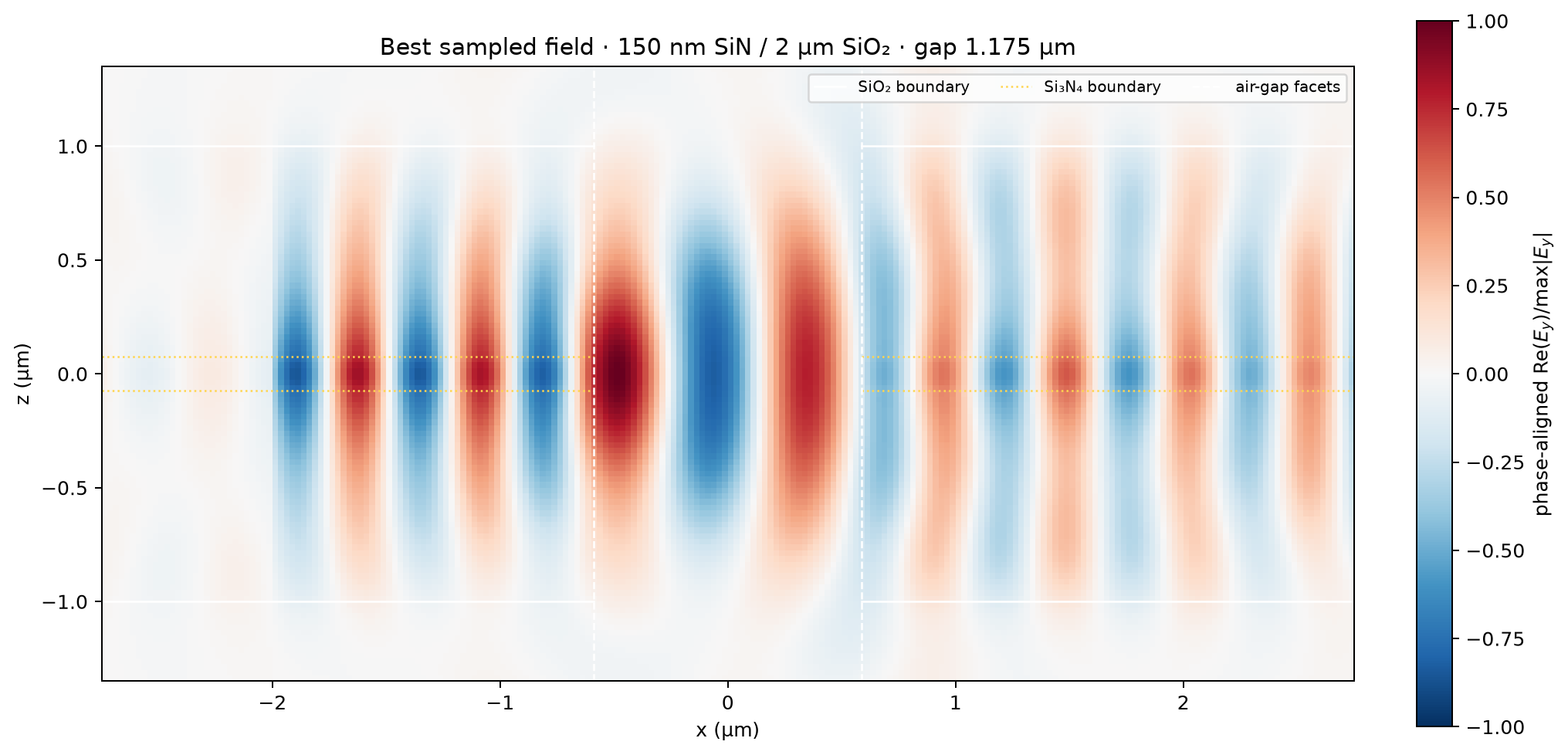
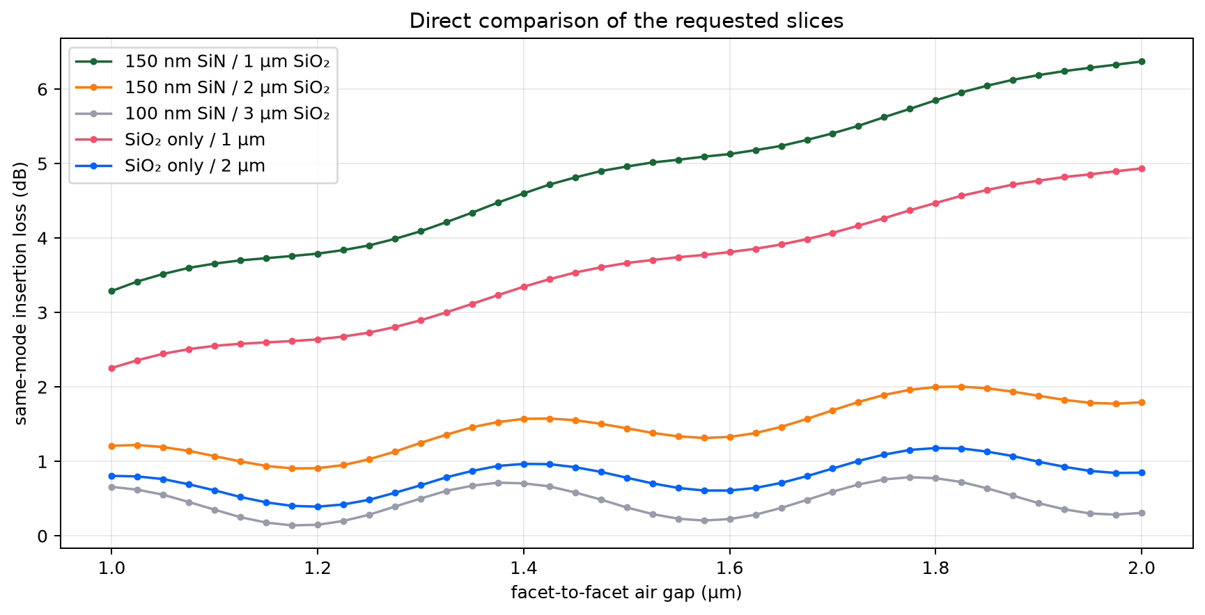
This is the seed study for the next optimization campaign. Two identical, coaxial square waveguides face one another across air at 780 nm. The composite slices use a square Si₃N₄ core (n=2.0) embedded in a finite square SiO₂ guide (n=1.44); the SiO₂-only controls remove that core. Air surrounds every guide. The incident field is the y-polarized fundamental mode of the complete guide; the output observable is the same forward mode in the opposite guide.
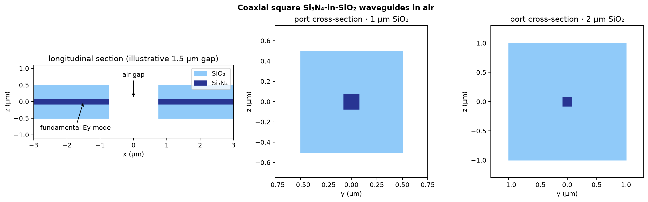
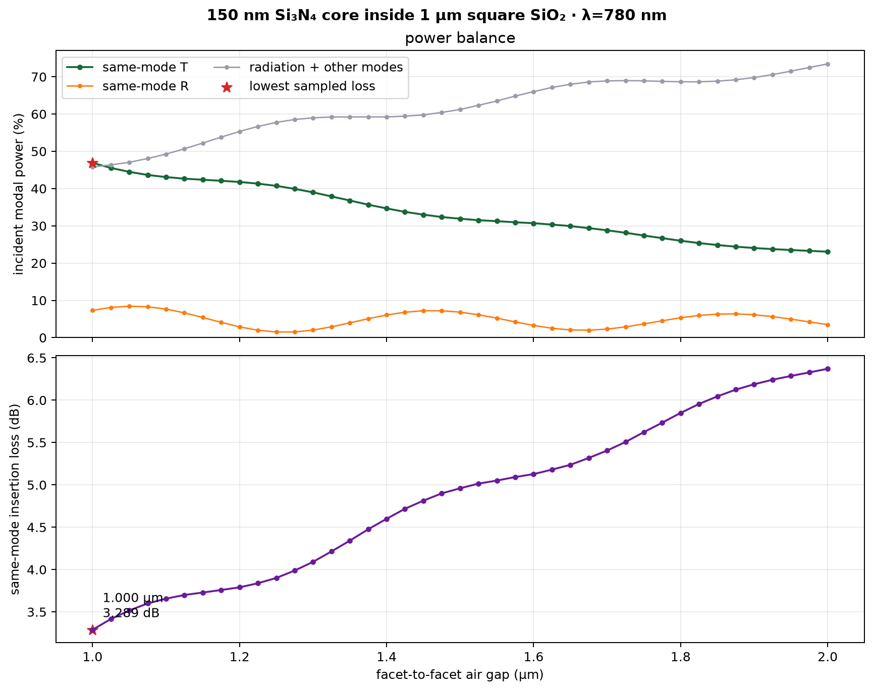
Requested 1 µm SiO₂ slice#
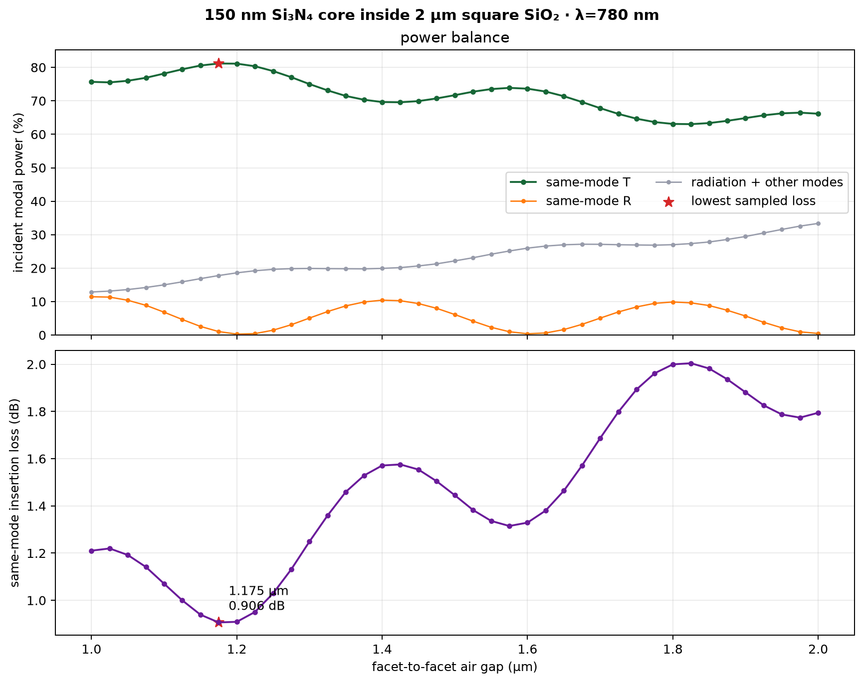
Requested 2 µm SiO₂ slice#
Direct comparison#
Added 100 nm SiN / 3 µm SiO₂ slice#
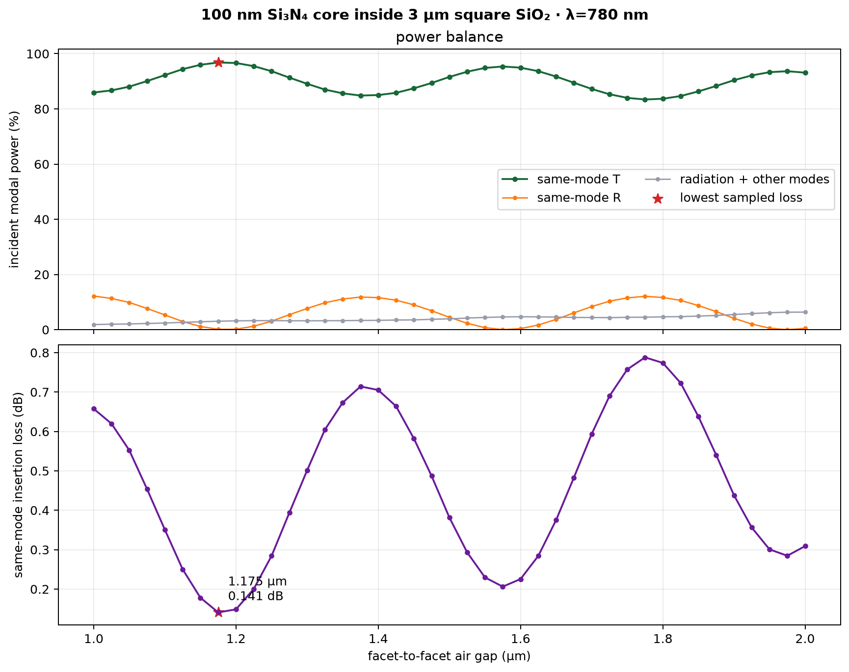
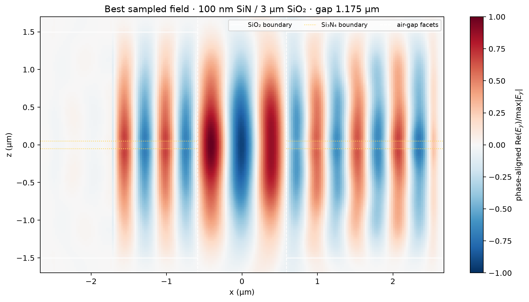
This follow-up uses the convergence-qualified 0.20 ps tape and compact 4.75 µm non-PML x domain. Its 3 µm square oxide still has 0.5 µm of air before the transverse PML on every side.
SiO₂-only controls#
These controls remove the Si₃N₄ core while retaining the same square-guide, fixed-port measurement.
1 µm square SiO₂#
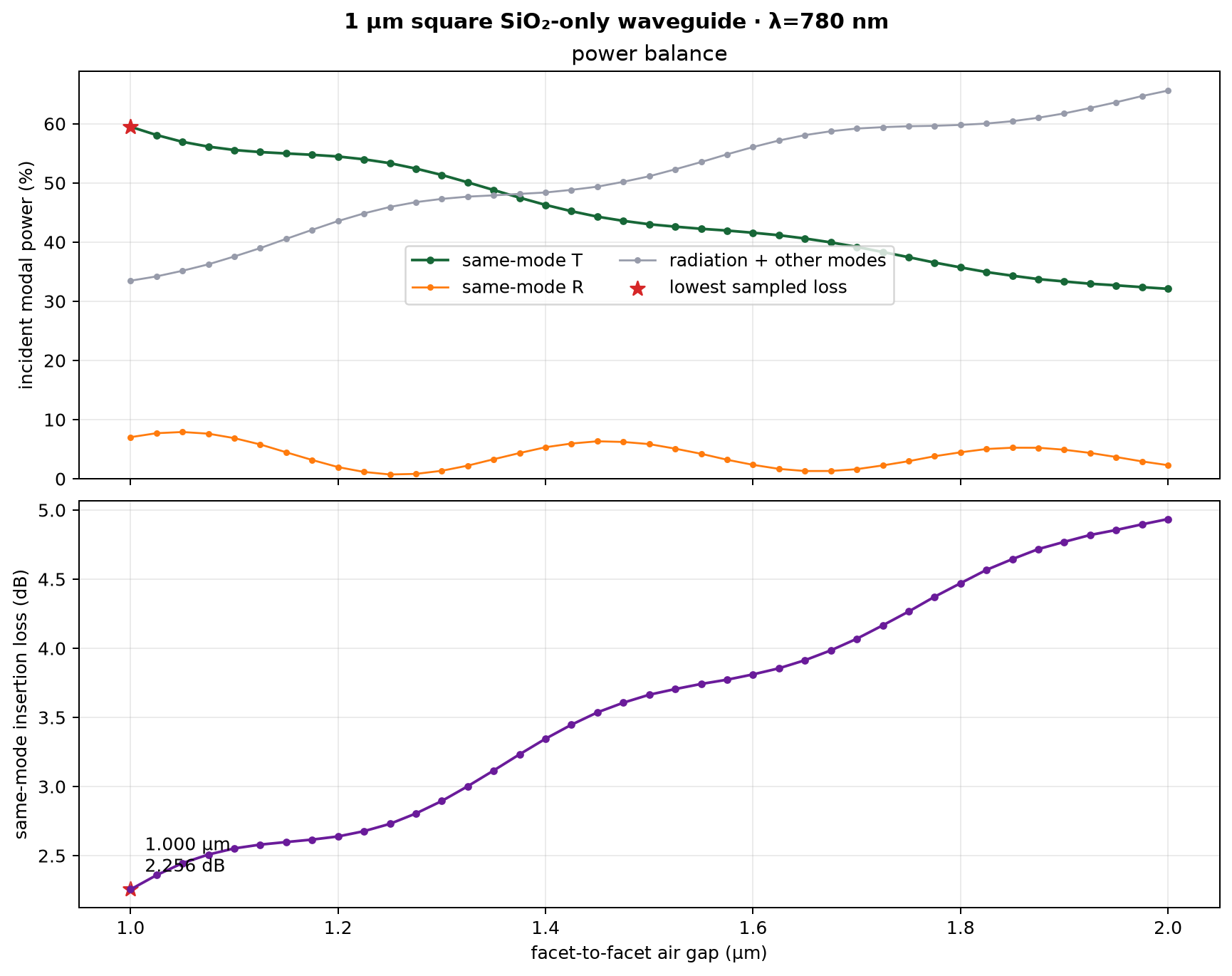
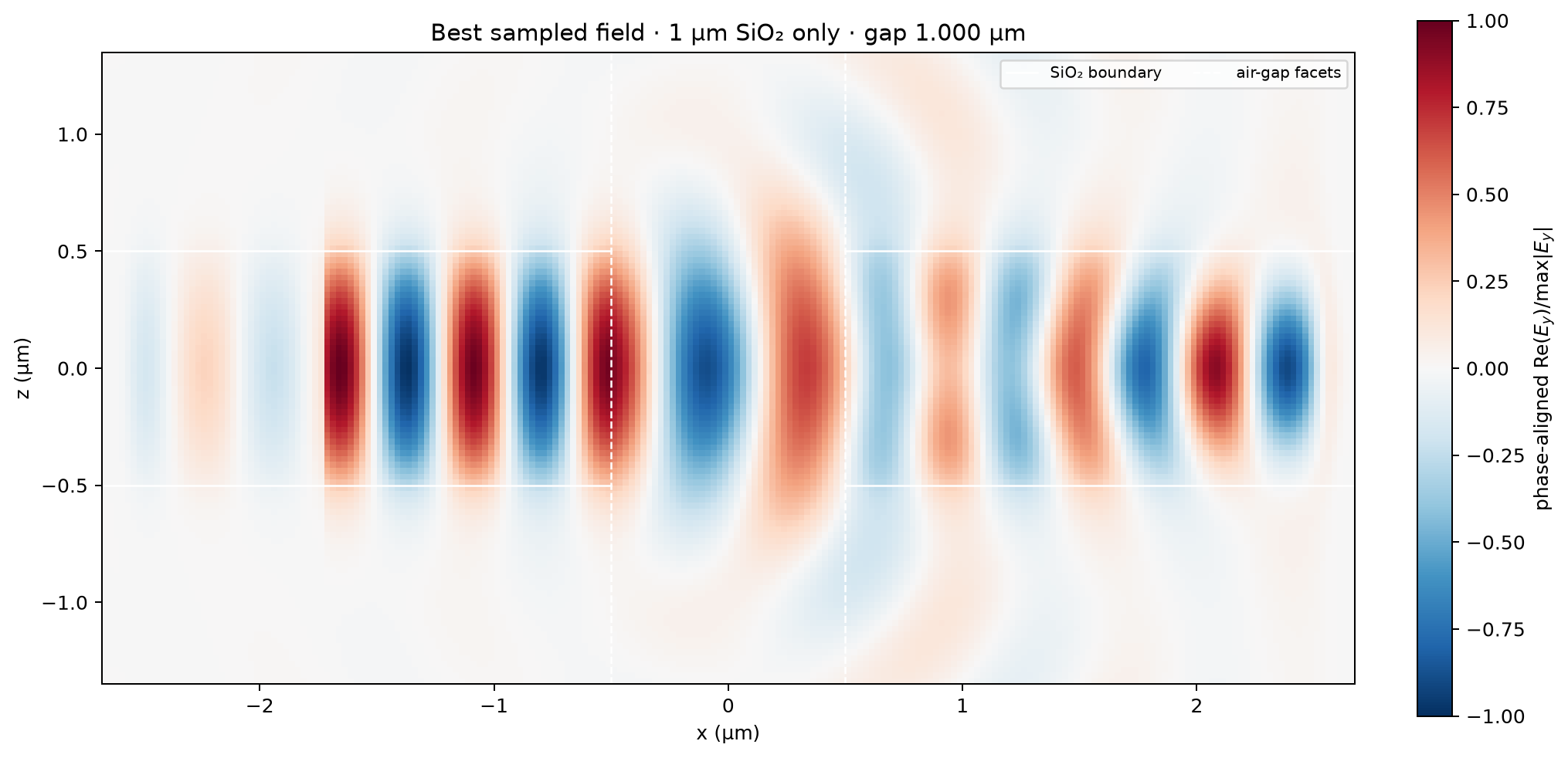
2 µm square SiO₂#
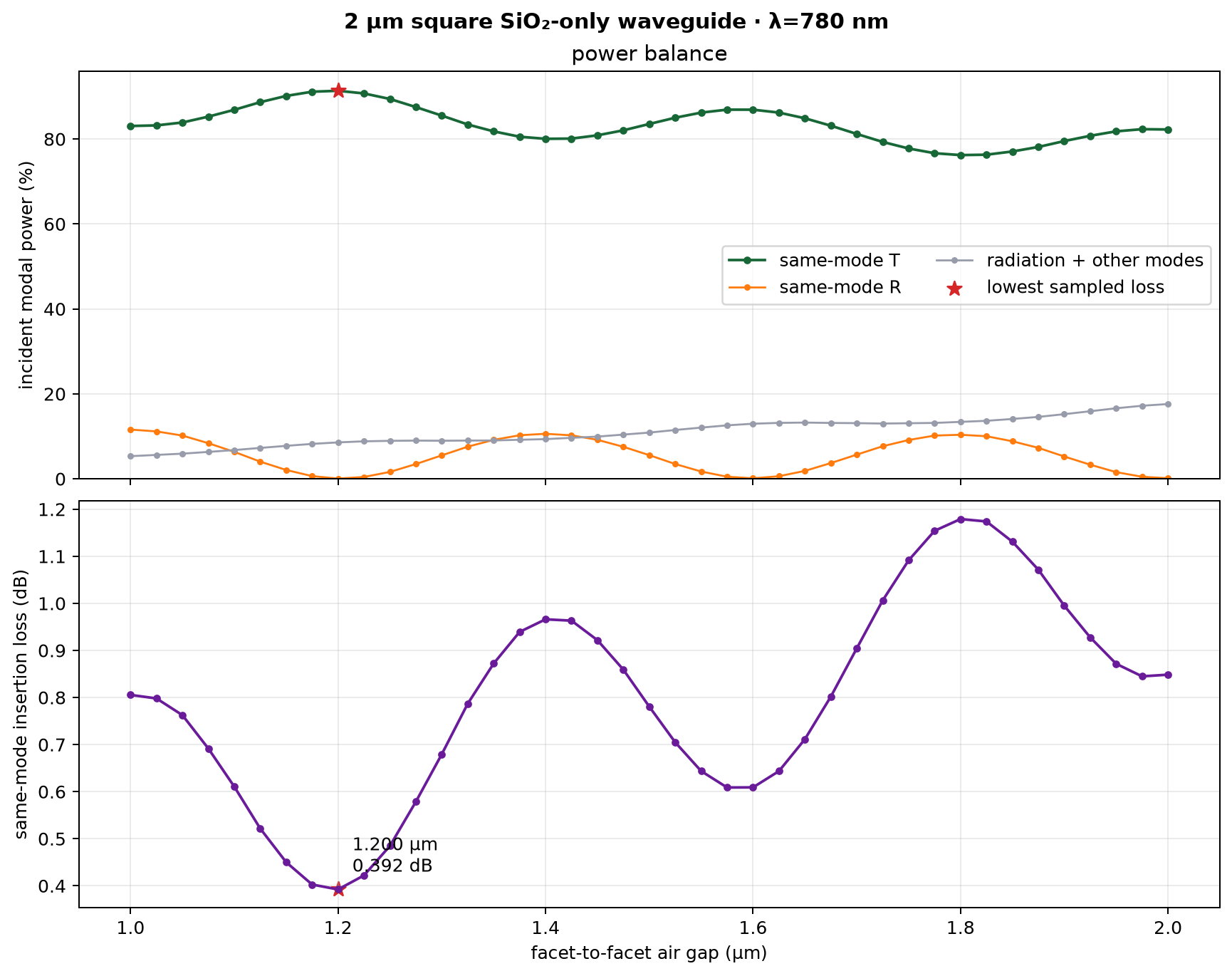
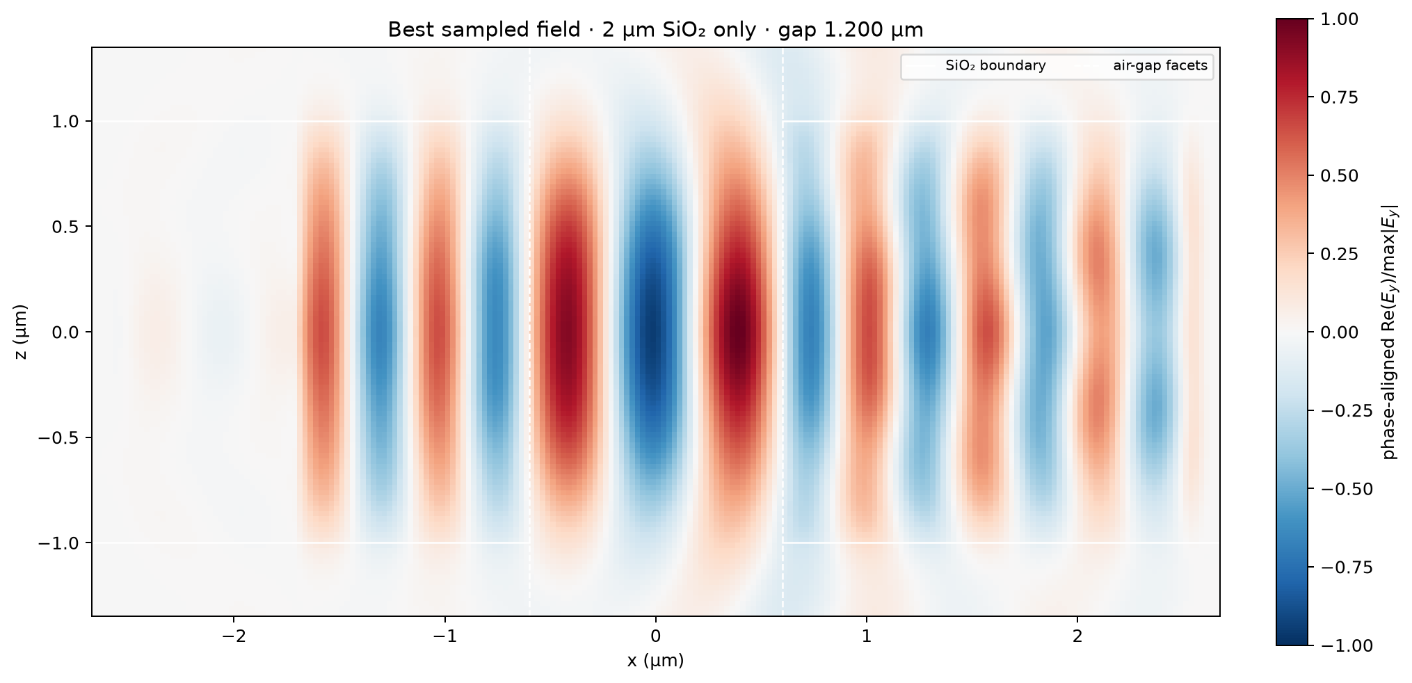
Lowest sampled loss#
SiN side (µm) |
SiO₂ side (µm) |
air gap (µm) |
T (%) |
loss (dB) |
same-mode R (%) |
radiation + other modes (%) |
|---|---|---|---|---|---|---|
0.150 |
1.000 |
1.000 |
46.894 |
3.2888 |
7.316 |
45.790 |
0.150 |
2.000 |
1.175 |
81.162 |
0.9065 |
1.049 |
17.789 |
0.100 |
3.000 |
1.175 |
96.809 |
0.1408 |
0.126 |
3.064 |
none |
1.000 |
1.000 |
59.490 |
2.2556 |
7.035 |
33.475 |
none |
2.000 |
1.200 |
91.364 |
0.3922 |
0.060 |
8.576 |
The optimum in this table is the best sampled 25 nm grid point, not a
continuous fit. Transmission is normalized by a directional input-mode
monitor. The residual is reported as raw 1-T-R; a negative value would flag
a numerical normalization problem rather than being silently clipped.
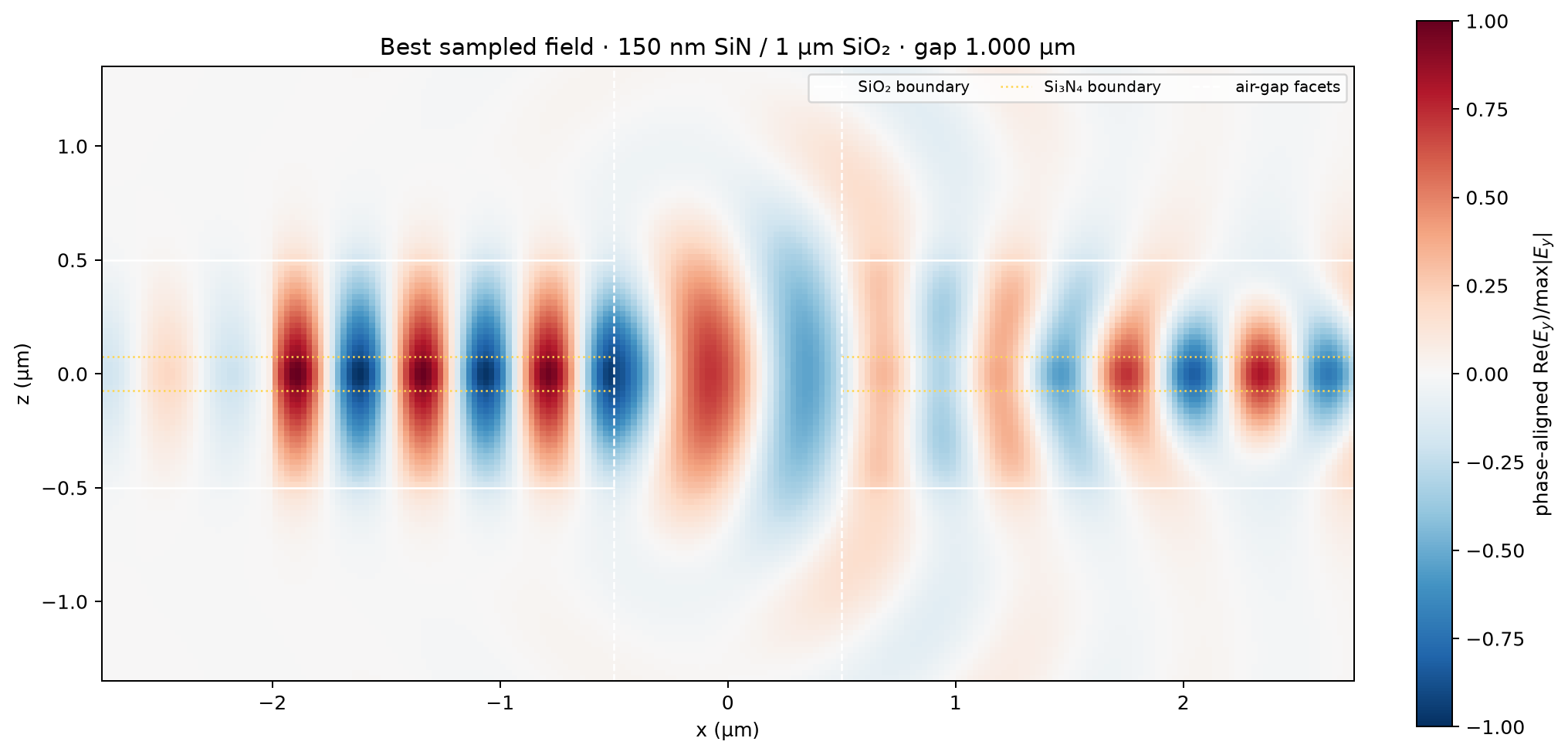
Field check#
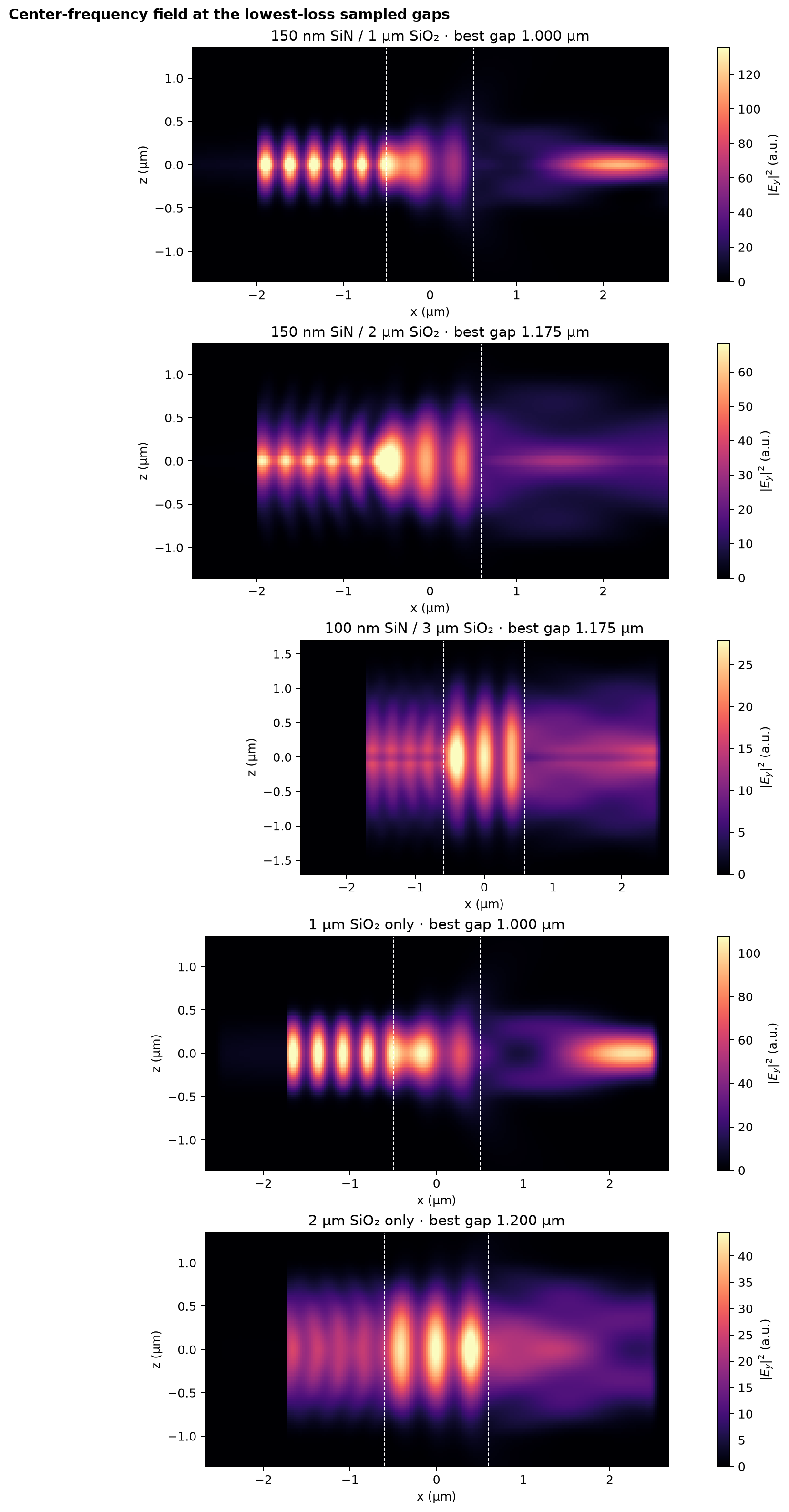
Numerical controls#
Continuous-guide calibration: 100.033% T and 0.00012% R. The compact 100 nm / 3 µm guide gives 100.000% T and 0.00294% R. The SiO₂-only guides give 100.125% T (1 µm) and 100.041% T (2 µm).
Full-domain versus y/z-symmetric transmission difference at the 1 µm gap: 1.192%.
0.20 ps versus 0.40 ps transmission difference at the 2 µm SiO₂ / 1.2 µm gap reference: 0.020%.
Compact- versus original-x-domain transmission difference at that reference: 0.038%.
The square guide has a degenerate fundamental polarization pair. The y-PEC and z-PMC walls select its y-polarized member. For the unrestricted full-domain audit, TE/TM sorting is disabled and the highest-effective-index fundamental pair is selected directly; this avoids accidentally comparing against a lower mode branch.
Numerical method#
Fixed 25 nm Yee grid; the 150 nm and 100 nm nitride cores span six and four cells, respectively, while the controls contain no nitride.
Component-aware Yee material discretization with subpixel-averaged facets.
Twelve-cell PML and y/z mirror symmetry; the normalized S-parameter ratio is retained by the modal overlaps. A one-way left-port source forbids direct x symmetry; a correct even/odd x decomposition would require two half-domain simulations.
A broadband Gaussian mode pulse is propagated for at most 0.40 ps in the original slices and 0.20 ps in the convergence-qualified compact extension, with relative-energy early termination in both cases.
Source and detector planes do not move with the air gap. This keeps port normalization identical across the sweep.
The artifact is three-dimensional in
(SiN side, SiO₂ side, air gap), so the remaining two parameter directions can be expanded without changing the measurement definition.
The complete setup and motivation are recorded in
METHOD.md.